Planar light beam orientation device

a technology of light beams and orientation devices, applied in dental articulators, instruments, educational models, etc., can solve problems such as time-consuming and frustrating procedures

Inactive Publication Date: 2000-04-18
BOARD OF RGT THE UNIV OF TEXAS SYST
View PDF17 Cites 12 Cited by
  • Summary
  • Abstract
  • Description
  • Claims
  • Application Information

AI Technical Summary

Problems solved by technology

This is a frustrating and

Method used


Image

  • Planar light beam orientation device
  • Planar light beam orientation device
  • Planar light beam orientation device

Examples


Embodiment Construction

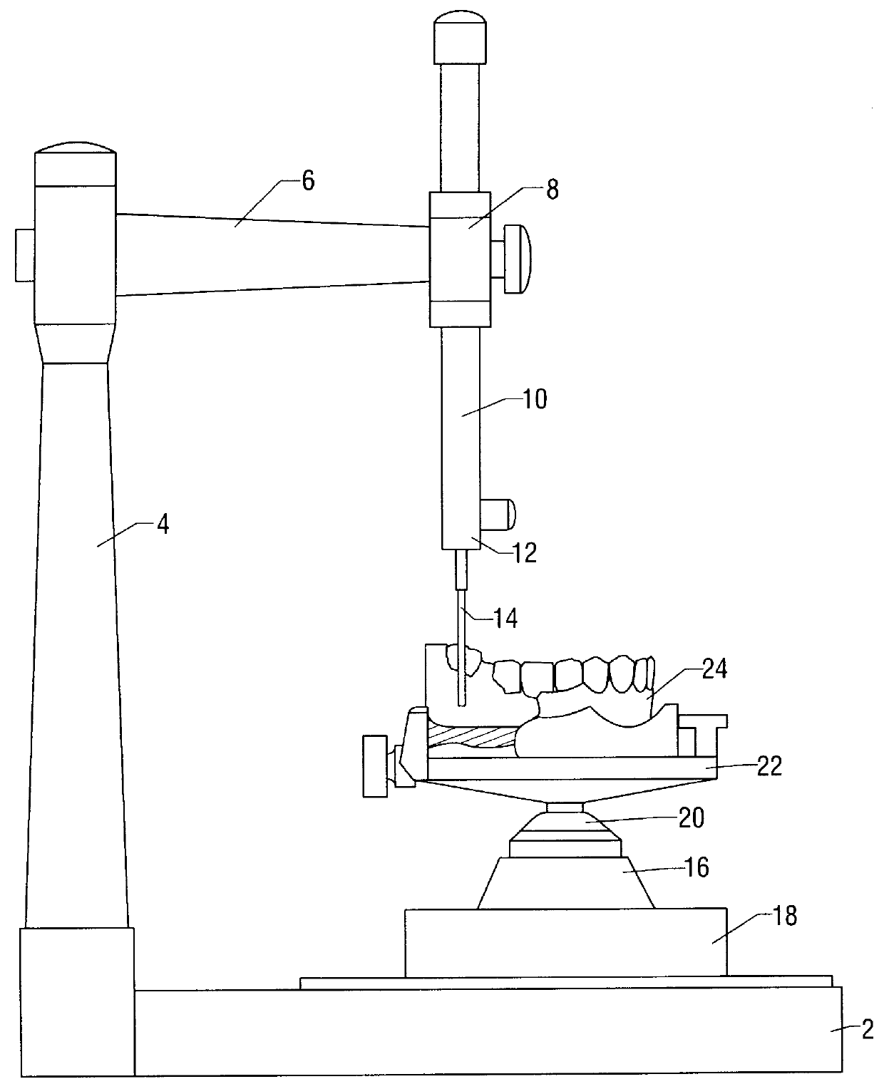
FIG. 1 illustrates a dental surveyor of the prior art. The dental surveyor illustrated in FIG. 1 includes a horizontal surveying platform 2 to which a vertical arm 4 is affixed. At the top of the vertical arm is an arm 6 projecting horizontally over the surveying platform. This horizontal arm 6 extends to the midpoint of the surveying platform 2. At the free end of the horizontal arm 6 is a receptacle 8 adapted for receiving a movable downward extending arm 10. The movable downward extending arm 10 extends vertically towards the surface of the surveying platform 2 and is adapted at its inferior end 12, i.e., the end projecting towards the surveying platform 2, to receive various attachments, including a marking stylus 14.

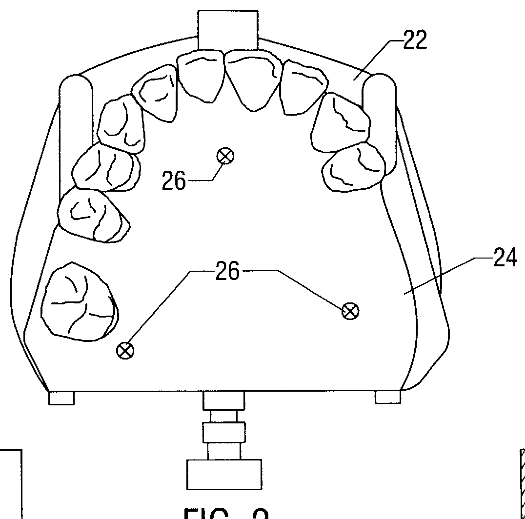
The surveying table 16 includes a base 18, a gimbal 20, and a platform 22 on which the dental cast 24 is mounted. Because of the inclusion of gimbal 20, platform 22 to which the dental cast 24 is mounted can be reversibly positioned in a given orientation. Gimbal 20...


PUM


Abstract

The present invention provides a planar light beam orientation device comprising a light source, a beam disperser, and a housing coupled to the light source and holding the beam disperser. The housing is configured to have a beam aperture configured to project a planar beam of light therefrom. The planar light beam orientation device of the present invention is capable of projecting a 360 DEG planar beam of light. The device is particularly useful in the orienting and reorienting of dental casts in a dental surveyor.

Description

1. Field of the InventionThe present invention relates generally to a planar light beam orientation device and more particularly to a planar light beam orientation device capable of projecting a 360.degree. planar beam.2. Description of the Related ArtIn the practice of dentistry, the making of removable partial dentures is a very exacting process. Careful planning on the part of the dentist is required prior to making the partial denture so that optimum fit and comfort are achieved for the patient.This planning process requires a careful analysis of models of the patient's teeth, also known as dental casts. This analysis is performed on a device known as a dental surveyor. A dental surveyor is comprised of a horizontal platform to which a vertical arm is affixed. At the top of the vertical arm is an arm projecting horizontally over the surveying platform. This horizontal arm extends to the midpoint of the surveying platform. At the free end of the horizontal arm is a receptacle ada...

Claims


Application Information

Patent Timeline
IPC IPC(8): A61C19/055A61C19/04G01B11/00G01C15/00A61C19/00
CPCG01B11/00A61C19/055
Inventor PHOENIX, RODNEY D.JONES, ROBERT E.
Owner BOARD OF RGT THE UNIV OF TEXAS SYST
Why Eureka
Try Eureka