Method of determining a turbulent condition in an aircraft

a technology of turbulent condition and aircraft, applied in the direction of instruments, clear air turbulence detection/forecasting, speed/acceleration measurement, etc., can solve problems such as the inability to use the system

Inactive Publication Date: 2014-03-13
GE AVIATION SYST LLC
View PDF15 Cites 24 Cited by
  • Summary
  • Abstract
  • Description
  • Claims
  • Application Information

AI Technical Summary

Problems solved by technology

Such a system is cumbersome, weighty, and the failure of a single sensor may disable the system.

Method used


Image

  • Method of determining a turbulent condition in an aircraft
  • Method of determining a turbulent condition in an aircraft
  • Method of determining a turbulent condition in an aircraft

Examples


Embodiment Construction

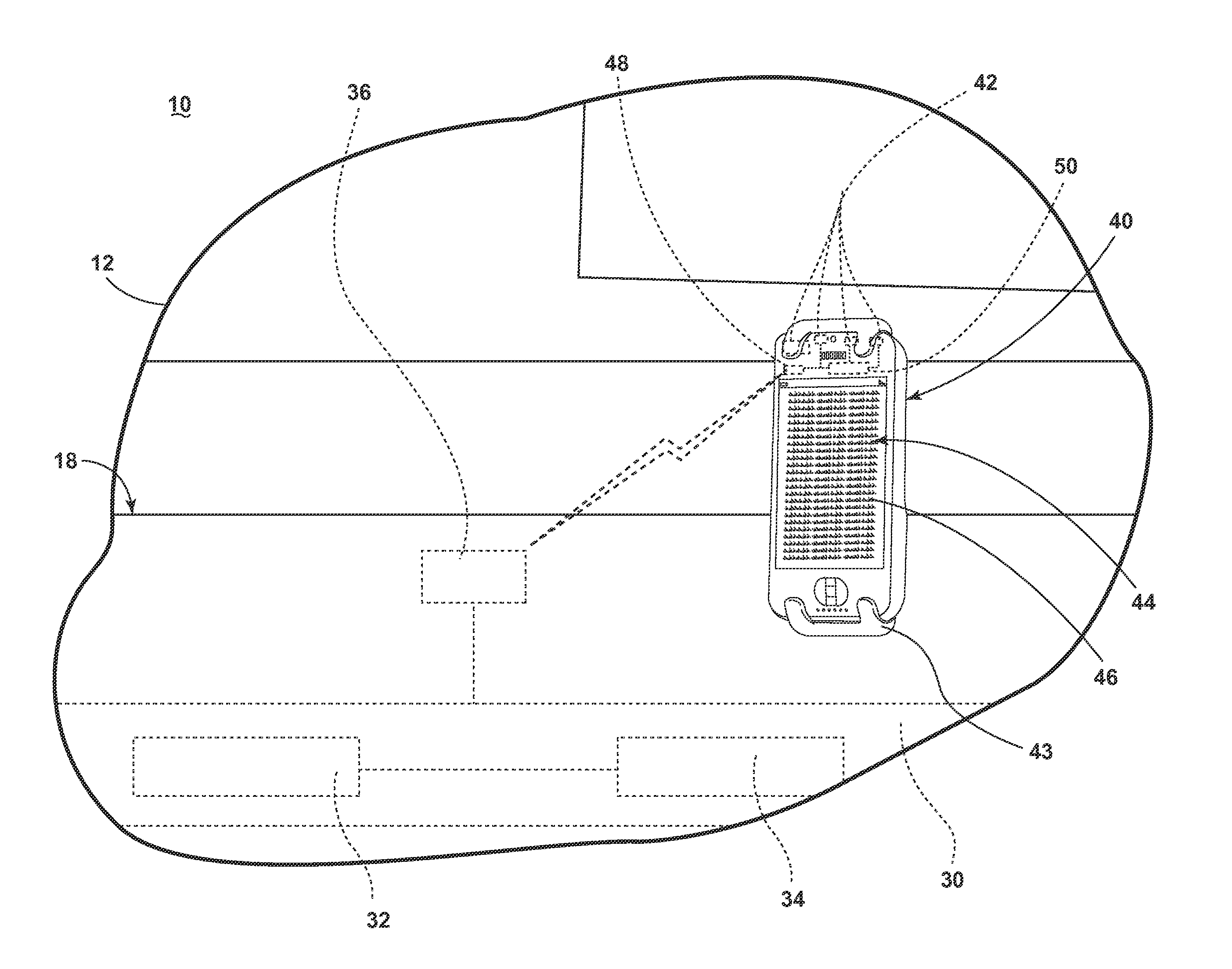
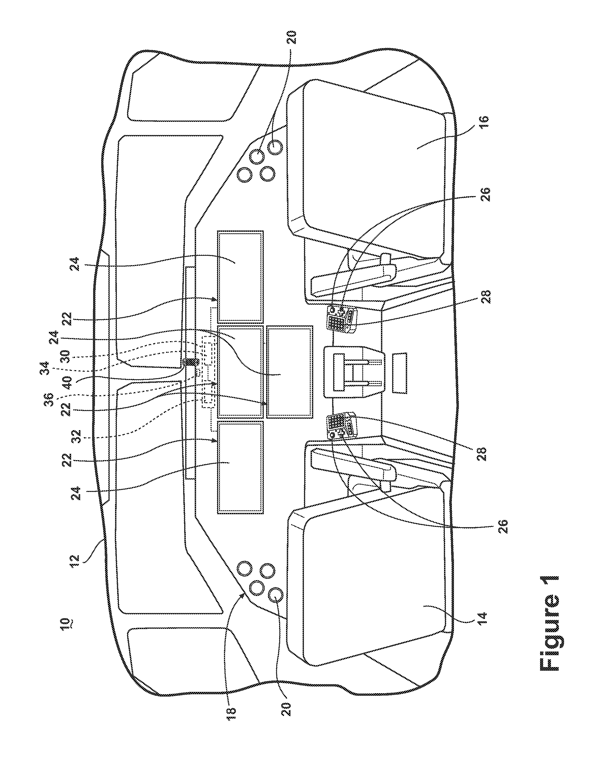
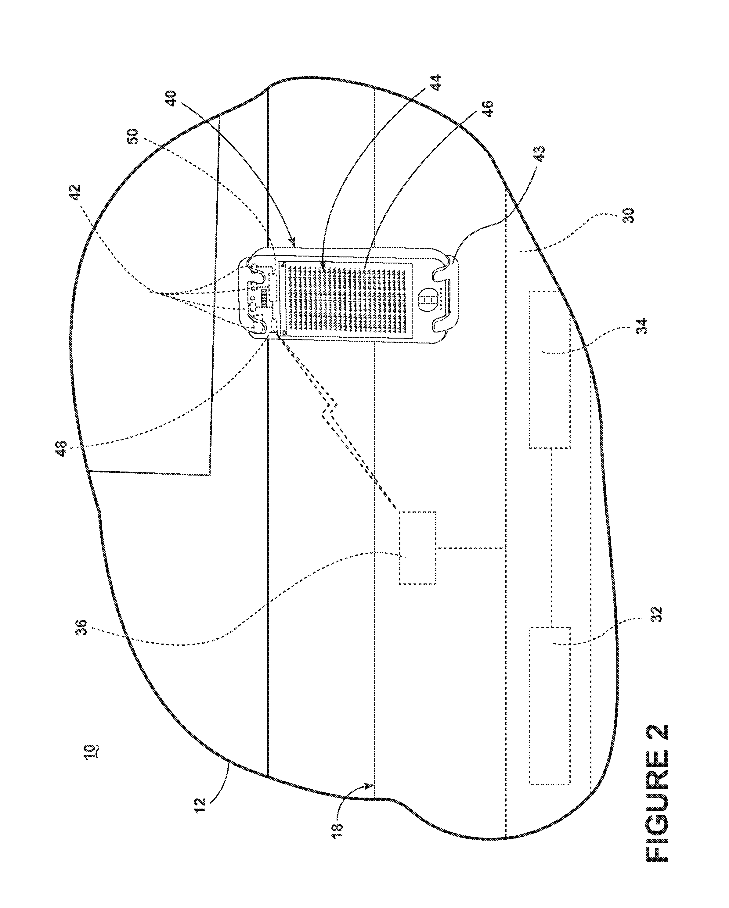
[0009]FIG. 1 illustrates a portion of an aircraft 10 having a cockpit 12. While a commercial aircraft has been illustrated, it is contemplated that embodiments of the invention may be used in any type of legacy aircraft, for example, without limitation, fixed-wing, rotating-wing, rocket, personal aircraft, and military aircraft. A first user (e.g., a pilot) may be present in a seat 14 at the left side of the cockpit 12 and another user (e.g., a co-pilot) may be present at the right side of the cockpit 12 in a seat 16. A flight deck 18 having various instruments 20 and multiple multifunction flight displays 22 may be located in front of the pilot and co-pilot and may provide the flight crew with information to aid in flying the aircraft 10.

[0010]The flight displays 22 may include either primary flight displays or multi-function displays and may display a wide range of aircraft, flight, navigation, and other information used in the operation and control of the aircraft 10. The flight ...


PUM


Abstract

A method of determining a turbulent condition in an aircraft with a handheld device where the handheld device has at least one of a gyroscope, seismometer, and an accelerometer where the method includes receiving an output from the at least one of the gyroscope, seismometer, and accelerometer while the handheld device is located within the aircraft and providing an indication of a turbulent condition.

Description

CROSS-REFERENCE TO RELATED APPLICATIONS[0001]This application claims priority under 35 U.S.C. §119 to Indian Patent Application No. 2787DEL2012, filed Sep. 7, 2012, the disclosure of which is incorporated herein by reference in its entirety.BACKGROUND OF THE INVENTION[0002]Contemporary aircraft may have a variety of sensors that may collect information and provide such information to the operators of the aircraft. For example, information from a range of sensors may be used to provide the flight crew with a display of the detected turbulence and the orientation of the aircraft. Such a system is cumbersome, weighty, and the failure of a single sensor may disable the system.BRIEF DESCRIPTION OF THE INVENTION[0003]In one embodiment, the invention relates to a method of determining a turbulent condition in an aircraft with a handheld device having at least one of a gyroscope, seismometer, and an accelerometer including receiving an output from the at least one of the gyroscope, seismome...

Claims


Application Information

Patent Timeline
Patent Type & Authority Applications(United States)
IPC IPC(8): B64D45/00
CPCB64D45/00G01W1/00G01W2001/003G01C23/00G08G5/0091G01C21/10
Inventor PEREIRA, FRAZER LESLIE
Owner GE AVIATION SYST LLC
Why Eureka
Try Eureka