
Apparatus and method for scheduling of ray tracing

a technology of ray tracing and apparatus, applied in the field of apparatus and method for processing ray tracing and scheduling of ray tracing operations, can solve the problems of occupying relatively more bandwidth, unable to perform traversal operations and intersection tests and the ray tracing method may not perform rendering at a high ra

Active Publication Date: 2014-03-20
SAMSUNG ELECTRONICS CO LTD
View PDF8 Cites 50 Cited by
  • Summary
  • Abstract
  • Description
  • Claims
  • Application Information

AI Technical Summary

Benefits of technology

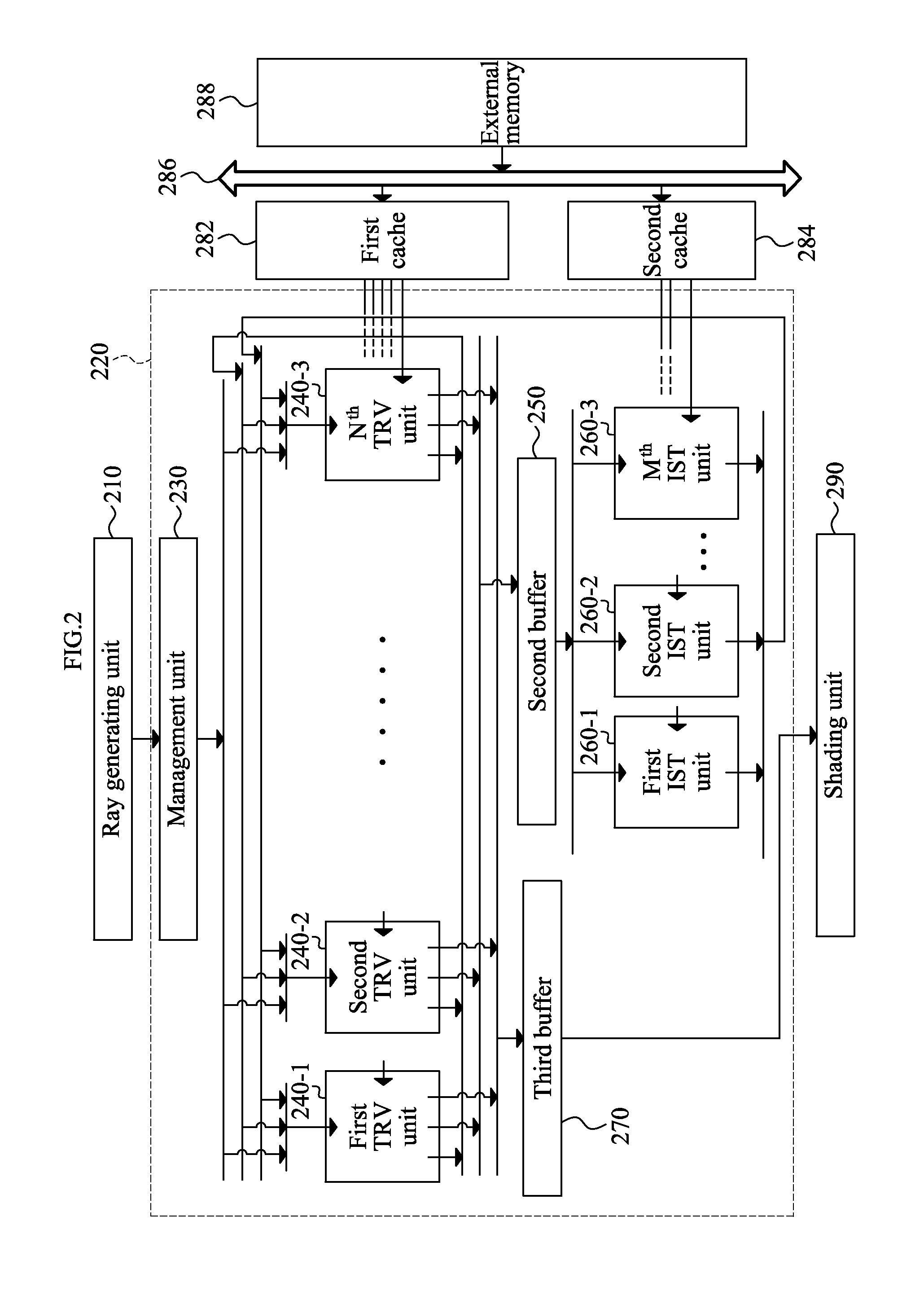
The patent describes a graphics processing apparatus for ray tracing that includes a plurality of traversal units to process rays of light in a space. The apparatus includes a management unit to distribute data of the rays to the traversal units. Each traversal unit processes the rays with respect to a subdivision of the space. The subdivision may be indicated by a node in a tree acceleration structure used for ray tracing. The apparatus may also include one or more intersection test units to perform an intersection test on the rays. The technical effect of the patent is to improve the efficiency and performance of ray tracing by distributing data of the rays to multiple units, and processing the rays with respect to subdivisions of the space.

Problems solved by technology

However, a significantly large amount of calculation may be utilized for ray tracing and thus, the ray tracing method may not perform rendering at a high rate.
That is, traversal operations and intersection tests are relatively computationally expensive, take up relatively more bandwidth, are relatively time consuming, and consume more power relative to other operations performed in ray tracing.
When data required for the traversal or the intersection test is absent within the cache, a long latency may occur while reading the data from an external memory.
The latency may also degrade the ray tracing performance.

Method used


Image

  • Apparatus and method for scheduling of ray tracing
  • Apparatus and method for scheduling of ray tracing
  • Apparatus and method for scheduling of ray tracing

Examples


Embodiment Construction

[0044]Reference will now be made in detail to embodiments, examples of which are illustrated in the accompanying drawings, wherein like reference numerals refer to the like elements throughout. Embodiments are described below to explain the present disclosure by referring to the figures.

[0045]Hereinafter, the term “ray” may indicate or refer to a “ray object” that is a target of ray tracing, a “data structure” that indicates a ray, “information of a ray”, or “data associated with a ray”. Accordingly, the terms “ray”, “ray object”, “ray structure”, “information of a ray”, and “data associated with a ray” may be interchangeably used with respect to each other.

[0046]Hereinafter, the term “shading unit” may also be referred to as a “shader”.

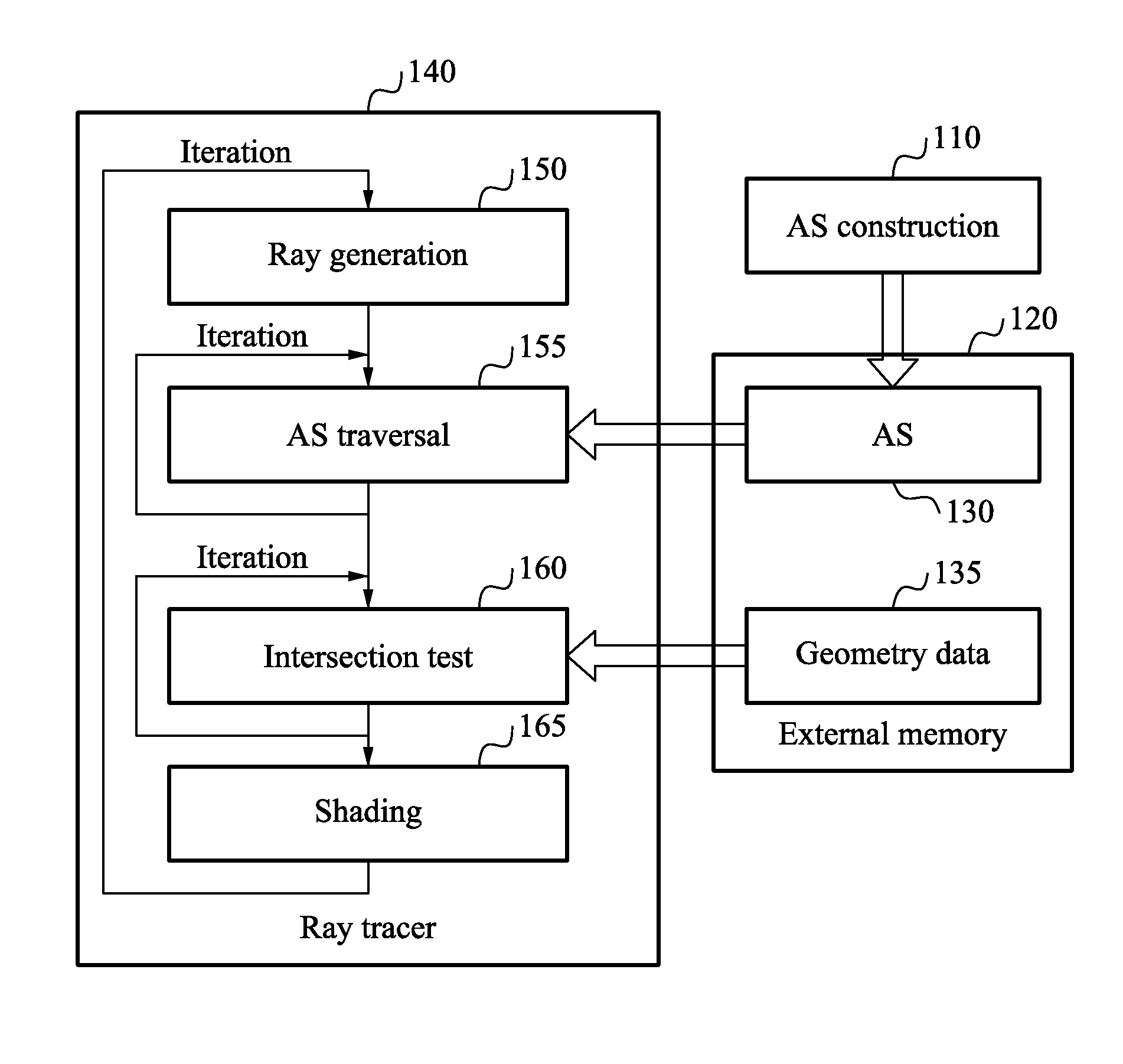
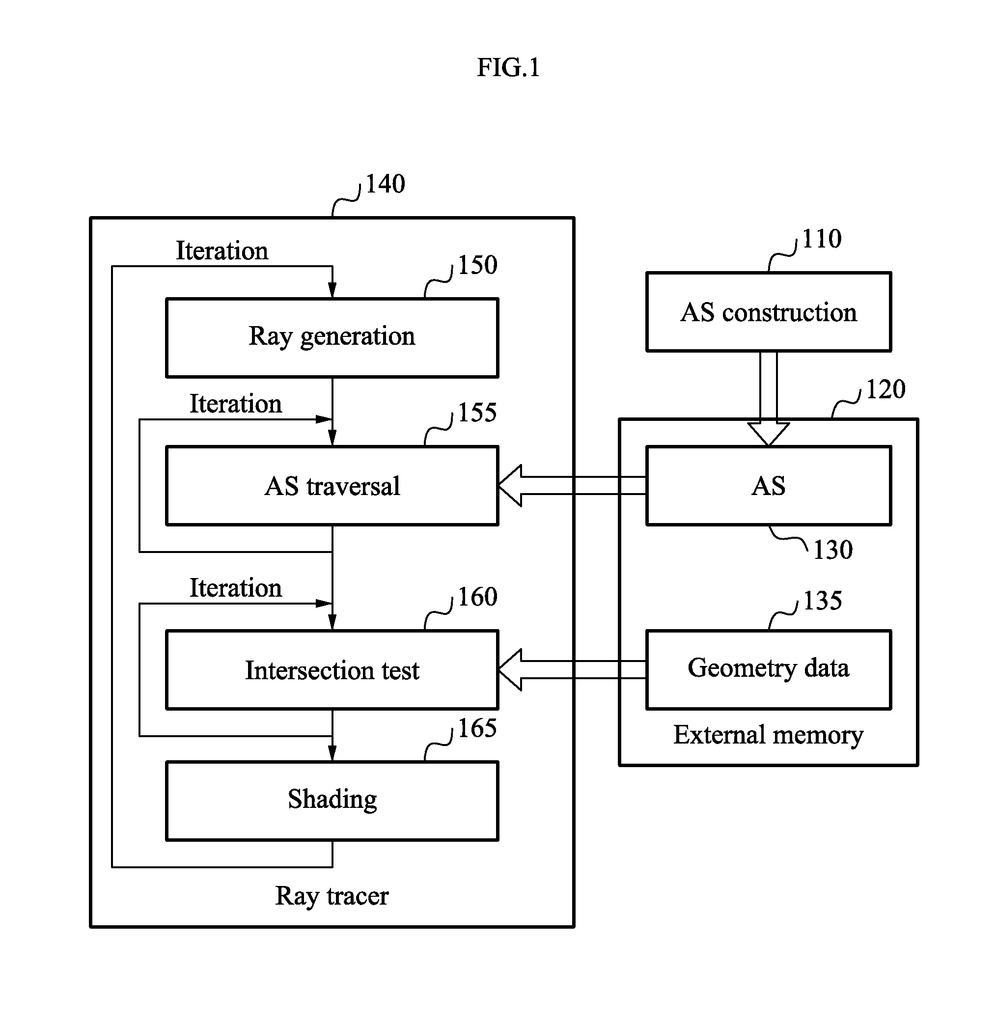
[0047]FIG. 1 illustrates a diagram to describe ray tracing according to an embodiment.

[0048]An acceleration structure (AS) construction 110 may indicate an operation or a process of constructing an AS 130 in an electronic apparatus or electronic devi...


PUM


Abstract

A graphic processing apparatus and method for processing ray tracing may include a plurality of traversal units to process traversal of a ray. A management unit of the graphics processing apparatus may distribute data of the ray processed by the graphics processing apparatus to the plurality of traversal units. Each of the plurality of traversal units may process ray traversal with respect to a subdivision of the entire space.

Description

CROSS-REFERENCE TO RELATED APPLICATIONS[0001]This application claims the priority benefit of Korean Patent Application No. 10-2012-0102709, filed on Sep. 17, 2012, in the Korean Intellectual Property Office, the disclosure of which is incorporated herein by reference.BACKGROUND[0002]1. Field[0003]One or more embodiments disclosed herein relate to an apparatus and method for graphics processing, and more particularly, to an apparatus and method for processing ray tracing and scheduling of ray tracing operations.[0004]2. Description of the Related Art[0005]Three-dimensional (3D) rendering may refer to an image processing process of synthesizing data of a 3D object into an image that is observed at a given viewpoint of a camera.[0006]As one example of a rendering method, a rasterization method may include generating an image while projecting a 3D object onto a screen may be employed. As another example of a rendering method, a ray tracing method may include generating an image by traci...

Claims


Application Information

Patent Timeline
Patent Type & Authority Applications(United States)
IPC IPC(8): G06T15/06
CPCG06T15/06
Inventor LEE, WON JONGSHIN, YOUNG SAMLEE, JAE DON
Owner SAMSUNG ELECTRONICS CO LTD
Learn More