Eureka AIR delivers breakthrough ideas for toughest innovation challenges, trusted by R&D personnel around the world.

Harmonic reducer with clutch function

a technology of harmonic reducer and function, which is applied in the direction of clutches, gearing, clutches, etc., can solve the problems of restricting the use of harmonic reducers

Active Publication Date: 2014-03-27
YEH CHUN SHEN
View PDF7 Cites 17 Cited by
  • Summary
  • Abstract
  • Description
  • Claims
  • Application Information

AI Technical Summary

Benefits of technology

The present invention solves the problem of fixed flexsplaines in reducers by using an elastic wall section in the mounting base and engaging a flexspine with a circular spline. This eliminates speed differences between the flexspine and the mounting base, providing additional stable support. The flexspine only deforms without rotating, reducing the output speed of the output shaft. The technical effect is an improved performance of the reducer with a fixed flexible spline.

Problems solved by technology

The circular spline and the output shaft of such harmonic reducer are limited by the resistance from the flexspline, thereby restricting the use of the harmonic reducer.

Method used


Image

  • Harmonic reducer with clutch function
  • Harmonic reducer with clutch function
  • Harmonic reducer with clutch function

Examples


Embodiment Construction

[0031]An embodiment of the present invention will be described in details with reference to the drawings so that this disclosure is thorough and fully conveys the concept of the invention to those who skilled in the art.

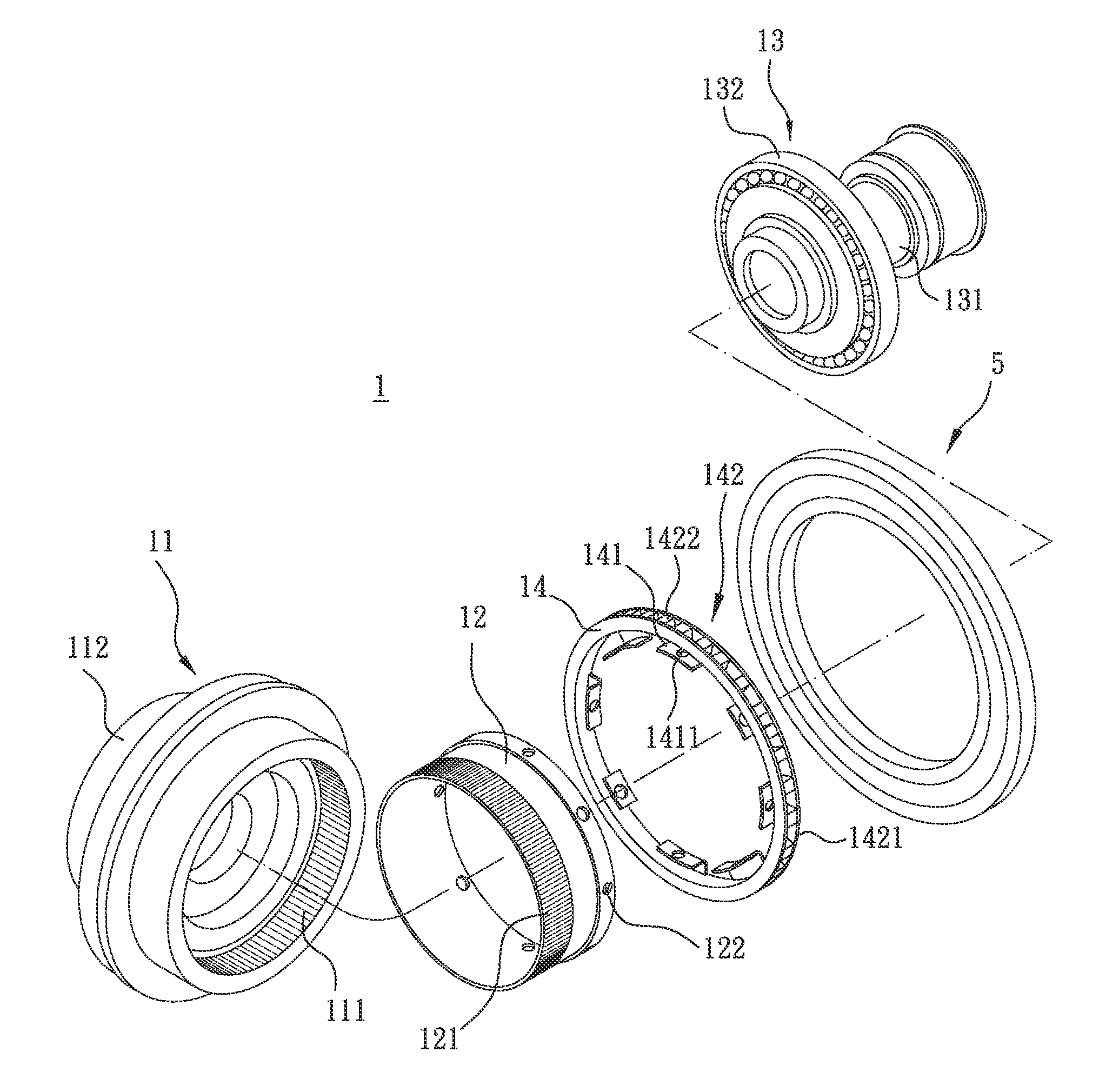
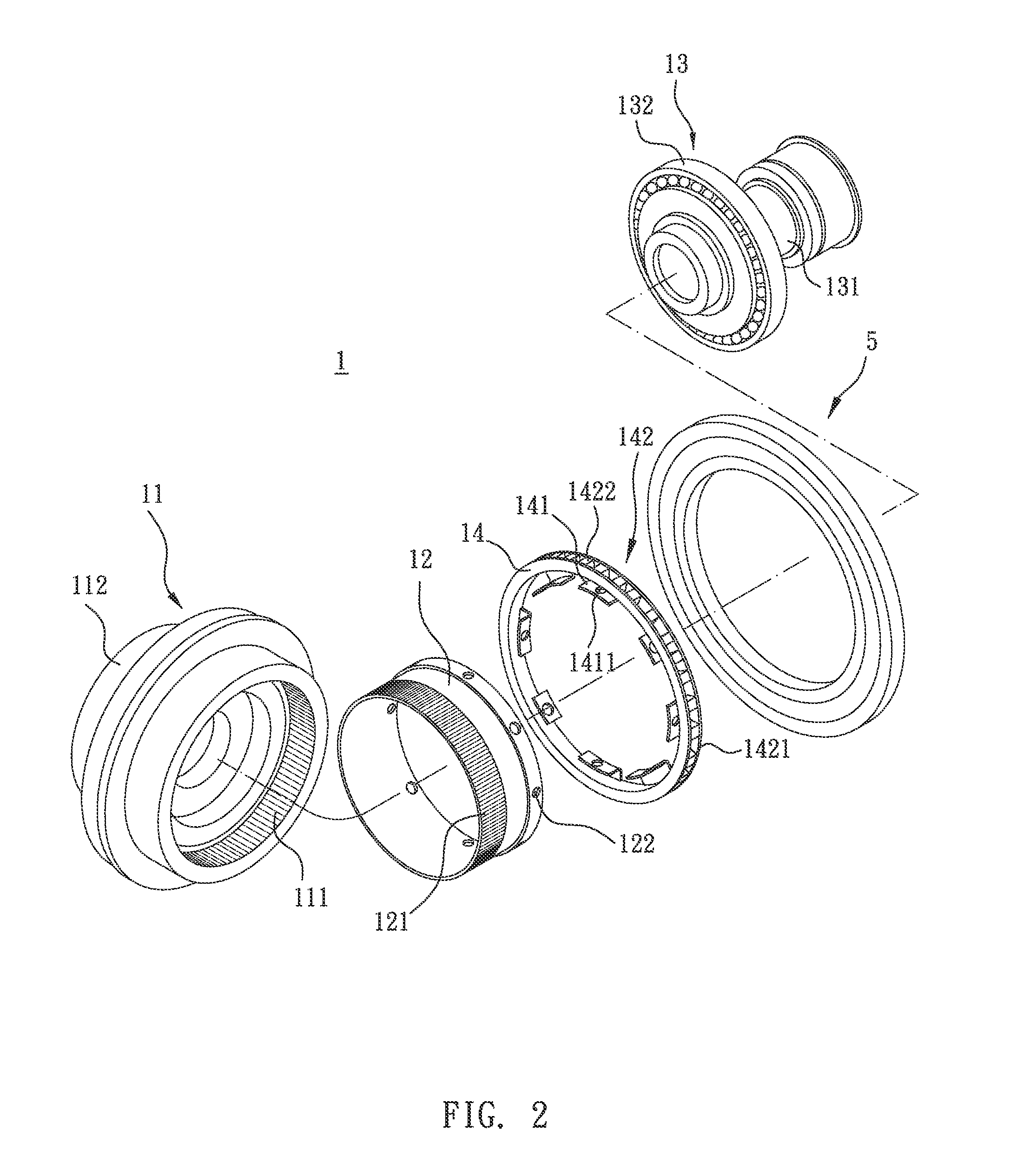
[0032]As shown in FIG. 2 and FIG. 3, the harmonic reducer 1 provided by the present invention includes: a circular spline 11, a flexspline 12, a wave generator 13 and a mounting base 14. The circular spline 11 has an inner wall defining an internal space, an internal gear 111 composed of a plurality of internal gear teeth is formed circumferentially on the an inner wall. The circular spline 11 is connected to an output shaft 112. In the preferred embodiment of the present invention, the output shaft 112 can be integrally formed at an end of the circular spline. A plurality of holes or screw holes can be disposed on the output shaft for installing other output devices.

[0033]The flexspline 12 can be manufactured into the precise shape and size with a tube material with...


PUM


Abstract

A harmonic reducer with clutch function includes a circular spline, a mounting base, a flexspline and a wave generator. When a power source drives the wave generator to rotate in a first direction, a one-way clutch engages to lock the mounting base so as to deform the flexspline and hence rotate the circular spline in the first direction. When an external force is applied to the output shaft in the first direction, the mounting base is driven by the flexspline so the one-way clutch disposed thereon is disengaged by a force in a second direction. At this moment, the rotation speed of the wave generator is equal to zero relative to the flexspline, so the wave generator can be driven by the circular spline to rotate along with the flexspline, and the central axel of the wave generator can be driven to rotate as well.

Description

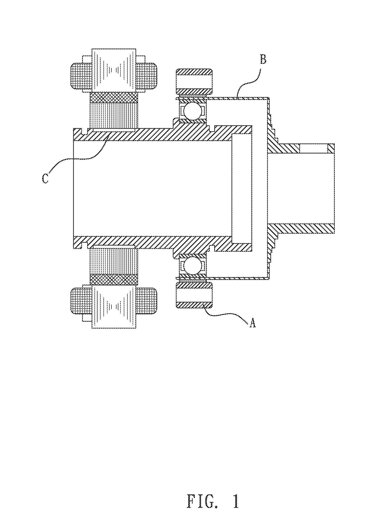
CROSS-REFERENCE TO RELATED APPLICATION[0001]This application claims the priority of Taiwanese patent application No. 101218625, filed on Sep. 26, 2012, which is incorporated herewith by reference.BACKGROUND OF THE INVENTION[0002]1. Field of the Invention[0003]The present invention relates to a harmonic reducer, more particularly, relates to a harmonic reducer that is fixed when being applied with a force in one direction, and is free to rotate when being applied with a force in another direction.[0004]2. The Prior Arts[0005]The harmonic reducer is a gear drive which uses flexible components to generate flexible mechanical wave to transmit power and motion. It is also called a “harmonic gear drive” (also known as the harmonic drive).[0006]FIG. 1 shows a conventional harmonic reducer, which includes three components: a circular spline A with an internal gear, a flexspline B with an external gear and a wave generator C. When the harmonic drive functions as a reducer, the conventional t...

Claims


Application Information

Patent Timeline
IPC IPC(8): F16H1/10
CPCF16H1/10F16H49/001F16D2041/0665Y10T74/19
Inventor YEH, CHUN-SHEN
Owner YEH CHUN SHEN
Why Eureka
Eureka Blog
Learn More