Float switch of a humidifier

a technology of float switch and humidifier, which is applied in the direction of operating means/release devices of valves, heating types, lighting and heating apparatus, etc., can solve problems such as annoying users, and achieve the effect of convenient separation and advanced usage safety

Active Publication Date: 2014-03-27
KUO TONG ELECTRICAL TECH HUI ZHOU CO LTD
View PDF0 Cites 21 Cited by
  • Summary
  • Abstract
  • Description
  • Claims
  • Application Information

AI Technical Summary

Benefits of technology

[0010]The water tank can be easily separated from the main body without risk of water leaking out, advancing usage safety.
[0011]The float switch is installed in the bottom of the water tank, able to detect water amount in the water tank so as to shut down the humidifier in case of less than safety amount, more assuring usage safety.
[0012]The float switch is provided with a pressing plate able to seal a water outlet of the water tank to prevent water from flowing out while the water tank is separated from the main body.

Problems solved by technology

However, as some water may still remain in the chamber of the float, and splash out to wet the body of a user if the water tank is not carefully separated from the body 1, somewhat annoying the user.

Method used


Image

  • Float switch of a humidifier
  • Float switch of a humidifier
  • Float switch of a humidifier

Examples


Embodiment Construction

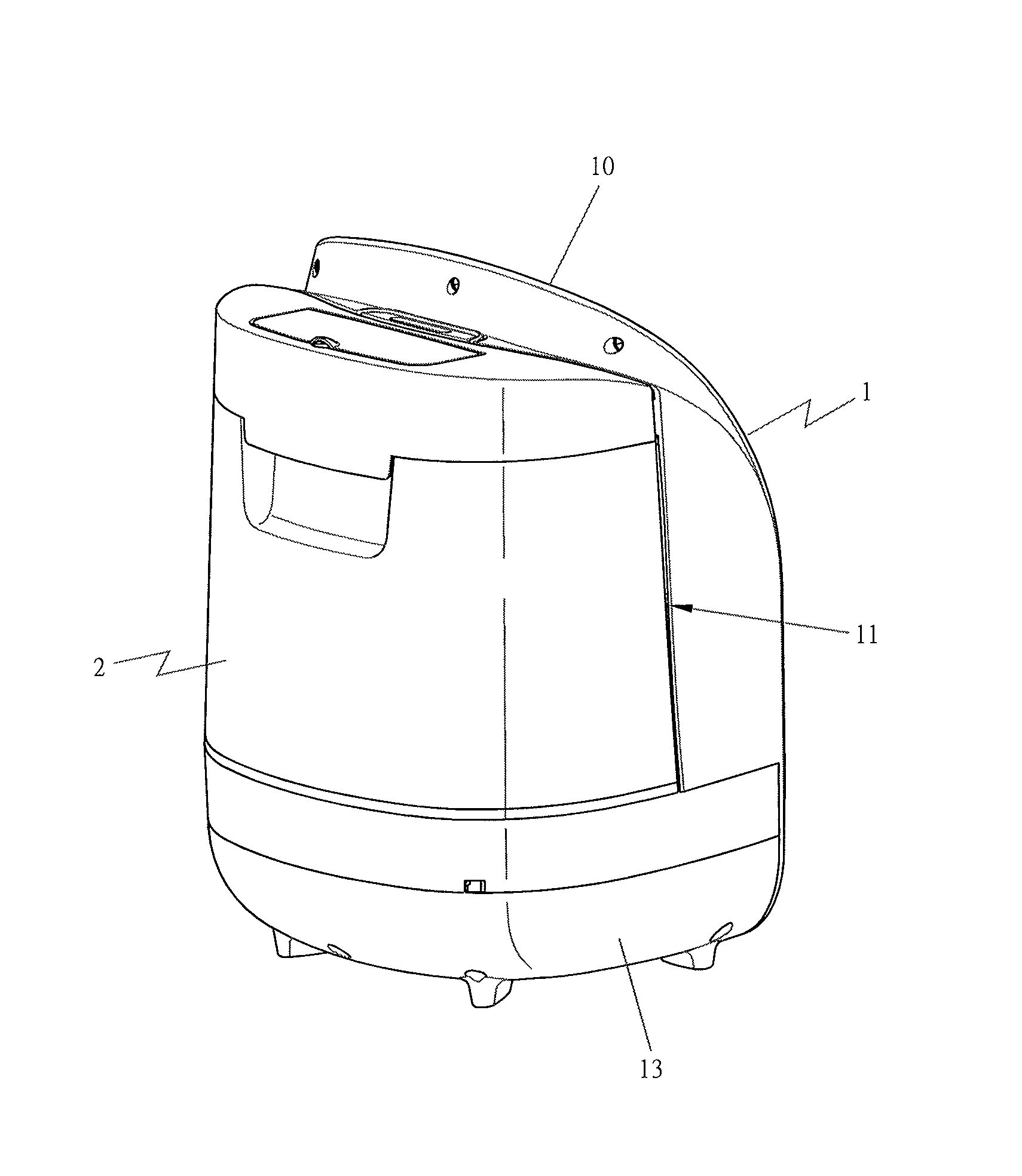
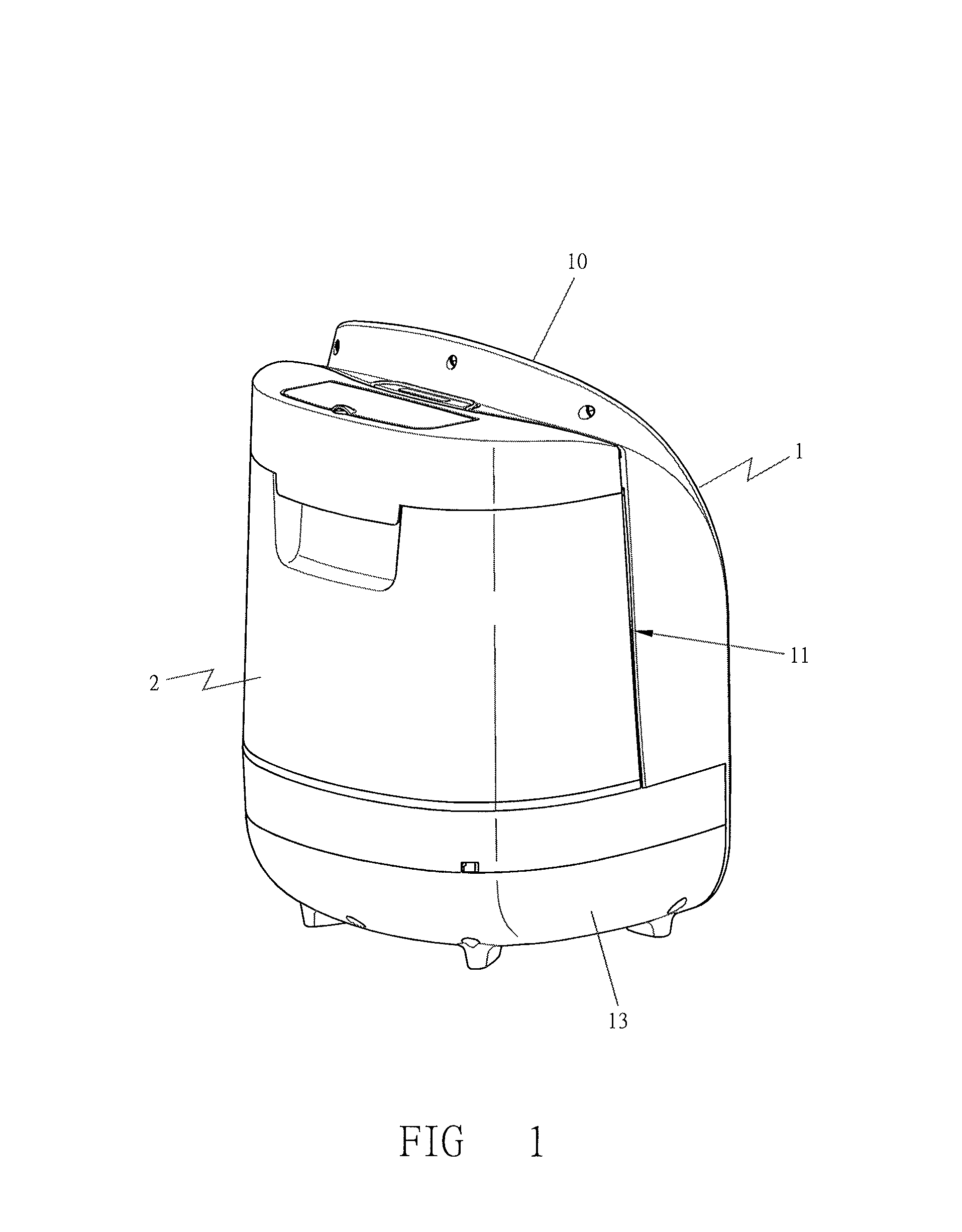
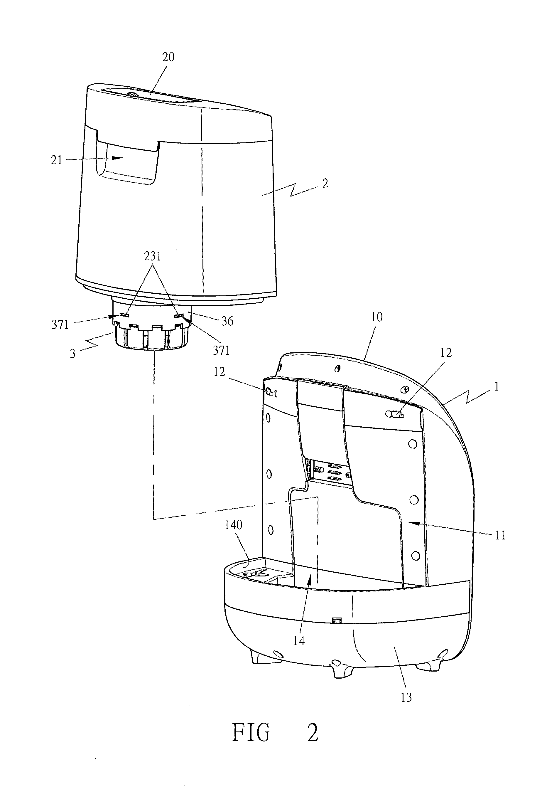
[0025]As shown in FIGS. 1 and 2, a preferred embodiment of a float of a humidifier in the present invention includes at least a main body 1, a water tank 2, and a float switch 3.

[0026]The main body 1 is provided with an operation panel 10 known as a conventional one, a water tank space 11 reserved at one side or a rear side for accommodating the water tank 2, and plural hooks 12 for fastening the water tank 2 to make it positioned stably. Further, formed at the bottom of the main body 1 is a base 13 provided with a water tank groove 14, which has a combining circumference 140 shaped the same as a bottom circumference of the water tank 2 and a water basin 141 employed to store water needed by a heater or a supersonic device (not shown in Figs. and described herein for being a conventional one), as shown in FIG. 3. And the water basin 141 is further provided with a projected portion 142 located at the bottom, with an angled notch 143 and a sloped surface 144 formed in the top of the p...


PUM


Abstract

A float switch of a humidifier at least includes a main body, a water tank and a float switch. The main body has a base located at a bottom and provided with a water tank groove and a water basin having a projected portion formed at a bottom. The water tank possesses a water outlet with plural ribs to engage with a float, a circumferential wall used to combine with a protective hood of the float switch, and a space formed between the water outlet and the circumferential wall for containing the float. The float switch is set between the water tank and the water basin, used to automatically fill water in the water basin by means of the float. When the water tank is separated from the main body, a compressing end of a pressing plate is to push up the float enabling a water stopper to seal the water outlet to prevent water form leaking outside.

Description

BACKGROUND OF THE INVENTION[0001]1. Field of the Invention[0002]This invention relates to a float switch of a humidifier, particular to one used in a drier land or season to increase indoor humidity to make a person's skin feel comfortable, provided with a float switch able to continuously fill water in a water basin to make the humidifier smoothly working and to seal a water outlet to keep water from leaking out in case of separating a water tank from a main body.[0003]2. Description of the Prior Art[0004]As disclosed in U.S. Pat. No. 6,259,860, a conventional float of a humidifier is mainly provided with a connect rod 25 fitting around with a coil spring 26 and having the top installed with a stopper 24. When a water tank 2 is assembled together with a body 1, as shown in FIG. 6 of the patent, the connect rod 25 is pushed up by a bottom base 120 of the body 1, forcing the stopper 24 to move upward and leave away from a water hole so as to let water in the water tank 2 flow down in...

Claims


Application Information

Patent Timeline
Patent Type & Authority Applications(United States)
IPC IPC(8): F16K31/18
CPCF24F2006/008F24F11/30F24F2110/00F24F6/00Y10T137/7358Y10T137/86196Y10T137/7323F16K31/20
Inventor HUANG, CHIN-CHENG
Owner KUO TONG ELECTRICAL TECH HUI ZHOU CO LTD
Why Eureka
Try Eureka