
Pfc LED driver capable of reducing flicker

Inactive Publication Date: 2014-03-27
WANG YEN HUI
View PDF1 Cites 15 Cited by
  • Summary
  • Abstract
  • Description
  • Claims
  • Application Information

AI Technical Summary

Benefits of technology

The present invention provides a PFC LED driver that can reduce flicki phenomenon caused by current ripple of LEDs, improve luminous efficiency without compromising power factor, and reduce flicker at a low cost and small size. The invention includes a controller that can dim the LEDs to reduce flicker. The driver utilizes a technology called PFC (which stands for power factor correction) to optimize power distribution and improve efficiency. The invention aims to offer an easy-to-design solution for reducing flicker in LED lighting applications.

Problems solved by technology

However, an output current flowing through an LED module will thereby tend to have a large current ripple, which causes an annoying flicker phenomenon and degrades luminous efficiency.
Although the two-stage PFC architecture is capable of providing a required power factor and reducing the current ripple of an output current, and thereby the flicker, for an LED module, it has the disadvantages of being expensive and bulky.
However, the very large capacitor is bulky and its performance on ripple reduction is still not good enough.

Method used


Image

  • Pfc LED driver capable of reducing flicker
  • Pfc LED driver capable of reducing flicker
  • Pfc LED driver capable of reducing flicker

Examples


Embodiment Construction

[0064]The present invention will be described in more detail hereinafter with reference to the accompanying drawings that show the preferred embodiments of the invention.

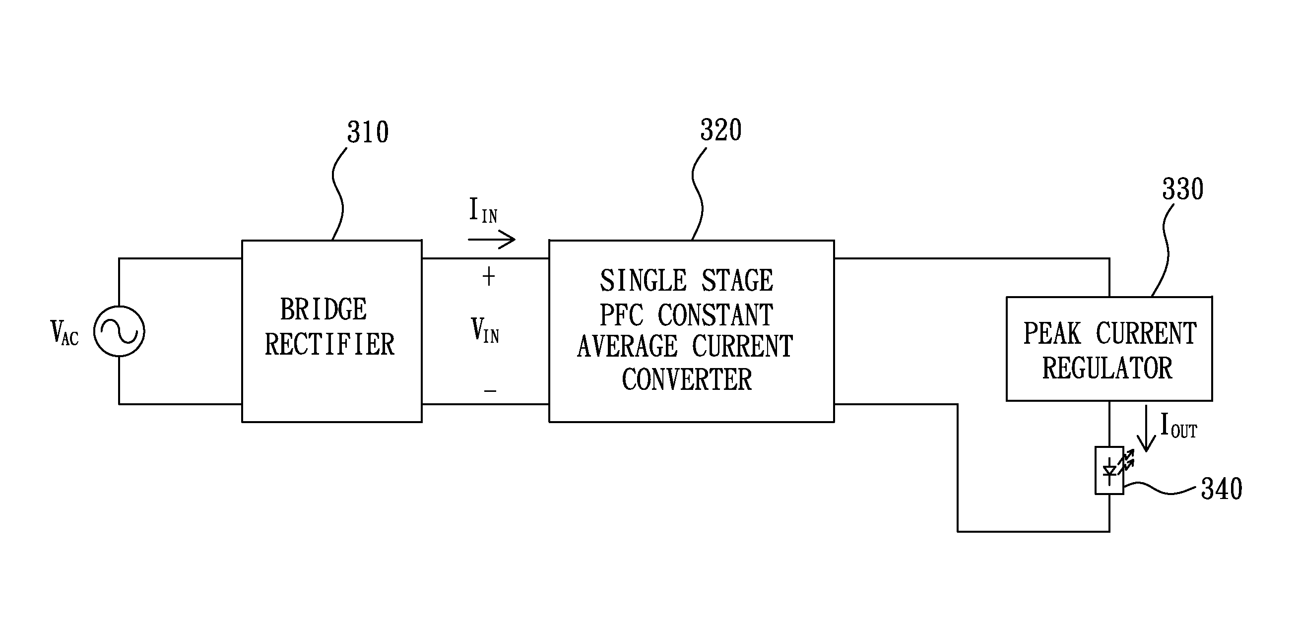
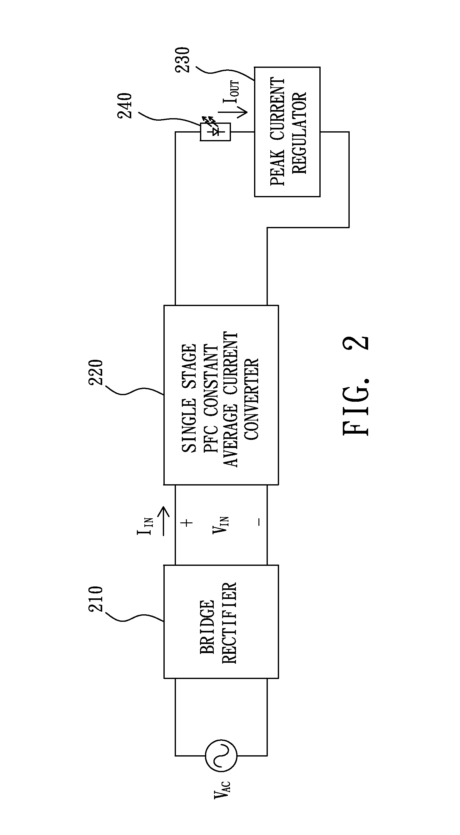
[0065]Please refer to FIG. 2, which illustrates a block diagram of a PFC LED driver capable of reducing flicker according to a preferred embodiment of the present invention. As illustrated in FIG. 2, the PFC LED driver capable of reducing flicker includes a bridge rectifier 210, a single stage PFC constant average current converter 220, and a peak current regulator 230, and an LED module 240 is driven by the PFC LED driver.

[0066]The bridge rectifier 210 is used to generate a full-wave-rectified line input voltage VIN according to an AC power VAC.

[0067]The single stage PFC constant average current converter 220, coupled with the bridge rectifier 210, is responsible for forcing an input current IIN to track the full-wave-rectified line input voltage VIN and regulating the average value of an output current IOUT at a f...


PUM


Abstract

A PFC LED driver capable of reducing flicker, including: a bridge rectifier, used to generate a full-wave-rectified line input voltage according to an AC power a single stage PFC constant average current converter, coupled with the bridge rectifier and used for forcing an input current to track the full-wave-rectified line input voltage and regulating an average value of an output current at a first preset value; and a peak current regulator, in series with an LED module to form a load for the output current to flow through, wherein the peak current regulator is used to regulate a peak of the output current at a second preset value, and the second preset value is higher than the first preset value.

Description

BACKGROUND OF THE INVENTION[0001]1. Field of the Invention[0002]The present invention relates to a PFC (power factor correction) LED (light emitting diode) driver, especially to a PFC LED driver capable of reducing flicker.[0003]2. Description of the Related Art[0004]In present LED lighting applications, LED drivers are generally required to provide a PFC (power factor correction) function, that is, to make an input current in phase with a full-wave-rectified line input voltage. However, an output current flowing through an LED module will thereby tend to have a large current ripple, which causes an annoying flicker phenomenon and degrades luminous efficiency.[0005]To reduce the current ripple of an LED current, one solution is to utilize a two-stage PFC architecture. Please refer to FIG. 1, which illustrates a block diagram of a prior art LED driver having a two-stage PFC architecture. As illustrated in FIG. 1, the prior art LED driver includes a bridge rectifier 110, a PFC convert...

Claims


Application Information

Patent Timeline
IPC IPC(8): H05B37/00H05B44/00H05B45/59
CPCH05B45/355Y02B20/30H05B45/397H05B45/59
Inventor WANG, YEN-HUICHANG, YU-WEN
Owner WANG YEN HUI
Features
  • Generate Ideas
  • Intellectual Property
  • Life Sciences
  • Materials
  • Tech Scout
  • Unparalleled Data Quality
  • Higher Quality Content
  • 60% Fewer Hallucinations
Learn More