Enhanced periscope

Active Publication Date: 2014-03-27
KENT PERISCOPES
View PDF5 Cites 8 Cited by
  • Summary
  • Abstract
  • Description
  • Claims
  • Application Information

AI Technical Summary

Benefits of technology

[0009]The mirror may have a single reflective surface which is rotated to reflect light either from the first reflector or from the display port. In a preferred embodiment, however, the mirror has two opposed reflective surfaces. In this case, in the first position of use a first reflective surface of the mirror may reflect light from the first reflector towards the viewing window and in the second position of use a second reflective surface of the mirror may reflect light from the display port towards the viewing window. According to this arrangement, the double-sided mirror can be arranged so that in either position of use and during transition between the two positions, the mirror blocks light from the display port from entering the optical path to the object window. This can be advantageous in preventing illumination of the object window by the electronic display, which could give away the position of the periscope in a military scenario. Moreover, with this arrangement, the space required in the direction of the optical paths for the mirror to move between the two positions of use is minimised, as the mirror is not required to pass through a position in which its plane is parallel to the optical paths.
[0010]

Problems solved by technology

However, such an arrangement is likely to increase the size of the periscope and therefore

Method used


Image

  • Enhanced periscope
  • Enhanced periscope
  • Enhanced periscope

Examples


Embodiment Construction

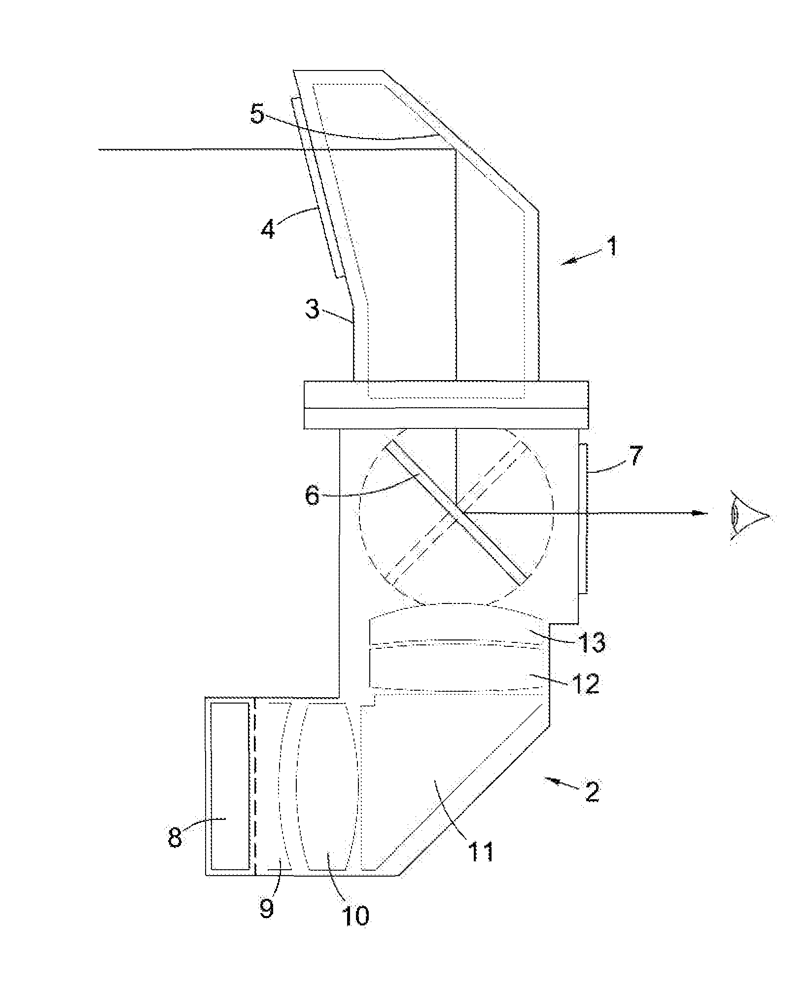
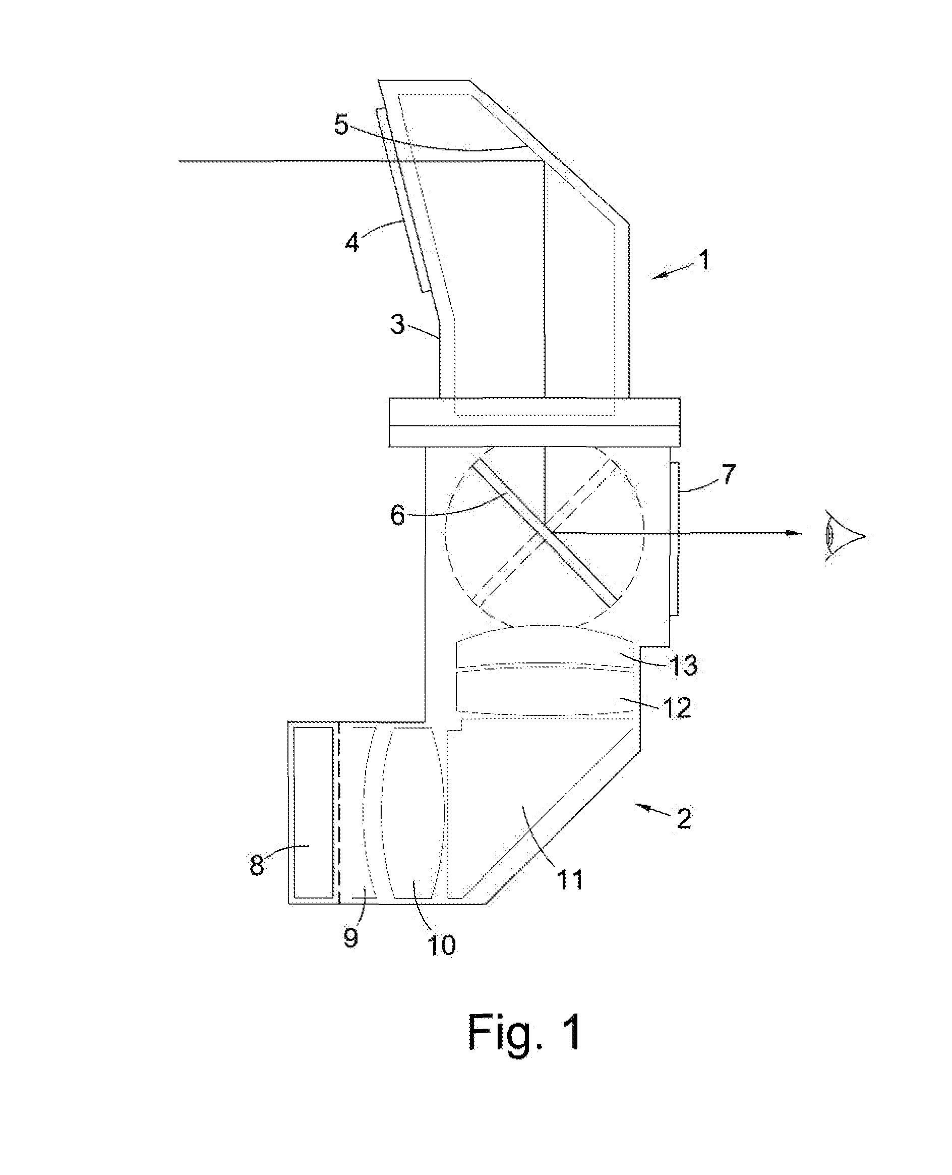
[0024]FIG. 1 is a sectional view of a periscope according to an embodiment of the invention. The periscope comprises an upper section 1 connected to a lower section 2. The upper section 1 comprises a housing 3 provided with a transparent window 4. Within the upper section 1, a mirrored surface 5 at an acute angle to the plane of the window 4 reflects light from the window 4 into the lower section 2.

[0025]The lower section 2 comprises a rotatable mirror 6 which is mounted for rotation within the housing of the lower section 2. The rotatable mirror 6 is mirrored on each of its major surfaces and is biased by a spring mechanism into two stable positions, represented in solid and phantom lines in FIG. 1. In the first stable position of the rotatable mirror 6, shown in solid lines in FIG. 1, light from the upper section 1 of the periscope is reflected by the mirror 6 through a viewing window 7 towards the user. In the second stable position of the mirror 6, shown in phantom lines in FIG....


PUM


Abstract

A periscope comprises an object window (4), a first reflector (5), a second reflector (6), a viewing window (7) and a display port for an electronic display (8). The first reflector (5) is arranged to reflect light from the object window (4) towards the second reflector (6). The second reflector (6) is selectively movable between a first position of use in which the second reflector (6) reflects light from the first reflector (5) towards the viewing window (7) and a second position of use in which the second reflector (6) reflects light from the display port towards the viewing window (7). The periscope provides a simple design that allows the user's view to be switched between an electronically generated image, such as night vision, and a purely optical image.

Description

[0001]This invention relates to a periscope.BACKGROUND[0002]Periscopes are used in a number of military applications to provide the occupants of a vehicle, such as a tank, with a view of the outside environment. In addition to the optical view from the periscope, such military vehicles are often also equipped with cameras that may provide digitally enhanced views of the outside environment, for example night vision or thermal imaging. It would be desirable to provide a periscope in which the user could switch between an external optical view and an electronically-generated view without changing the viewing position. Such a periscope is desirably relatively compact in order to allow retrofitting into existing vehicles without affecting the comfort or ease of exit of the user.BRIEF SUMMARY OF THE DISCLOSURE[0003]In accordance with the present invention there is provided a periscope comprising an object window, a first reflector, a second reflector, a viewing window and a display port ...

Claims


Application Information

Patent Timeline
IPC IPC(8): G02B23/08
CPCG02B23/08F41H5/266G02B23/10G02B26/0816
Inventor OWEN, GARY
Owner KENT PERISCOPES
Why Eureka
Try Eureka