Regenerators Placement Mechanism For Wavelength Switched Optical Networks

a technology of wavelength switched optical networks and generators, applied in the field of telecommunication networks, can solve the problems of complex network engineering and planning, scaling up or/and providing new services in the point-to-point network, and requiring extensive simulation and testing, and achieves automatic establishment of new connections, optimized network response time, and adequate quality of selected trails

Inactive Publication Date: 2014-03-27
LUCENT TECH INC +1
View PDF2 Cites 16 Cited by
  • Summary
  • Abstract
  • Description
  • Claims
  • Application Information

AI Technical Summary

Benefits of technology

[0012]It is also an object of the invention to optimize regenerator placement and wavelength assignment for efficient use of regenerators and wavelengths available in the network, while maintaining a very efficient time-to-service.
[0016]Advantageously, the regenerator placement method according to the invention allows fast, automatic establishment of new connections based on the current network architecture, connectivity and loading and also on conditions in the connection request. Selection of regenerator sites and of the wavelengths used on each regenerator segment is performed with optimal use of current network resources, while ensuring that the quality of the selected trail is adequate for the respective call. The method provides for both distance and performance balancing, and it optimizes the network response time.

Problems solved by technology

In addition, the pt-pt network requires duplication of equipment for protection / restoration in case of fault.
As a result, the configuration of a typical node of a point-to-point network is very complex.
Furthermore, scaling-up or / and providing new services in a point-to-point network requires very complex network engineering and planning involving extensive simulation and testing.

Method used


Image

  • Regenerators Placement Mechanism For Wavelength Switched Optical Networks
  • Regenerators Placement Mechanism For Wavelength Switched Optical Networks
  • Regenerators Placement Mechanism For Wavelength Switched Optical Networks

Examples


Embodiment Construction

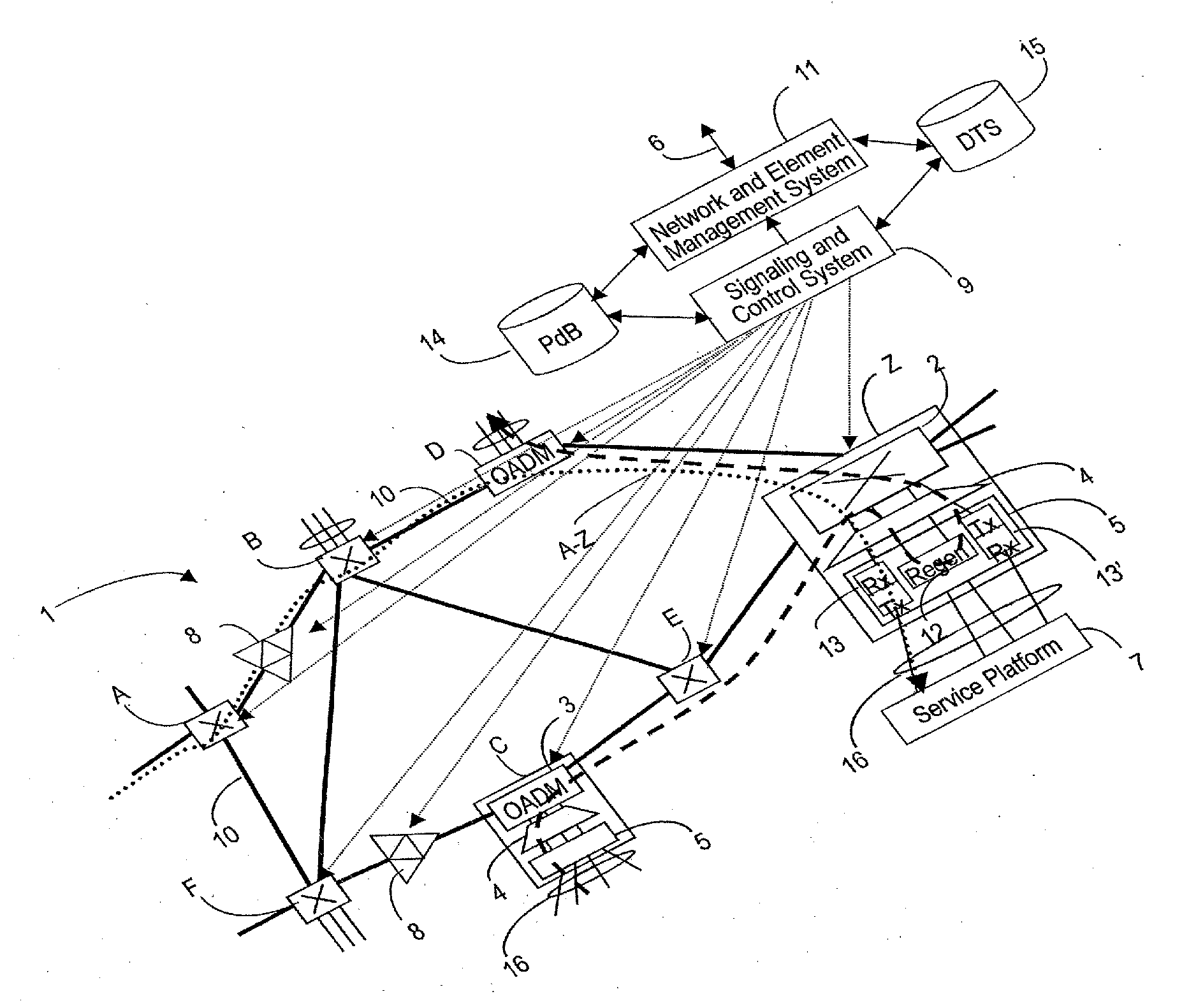
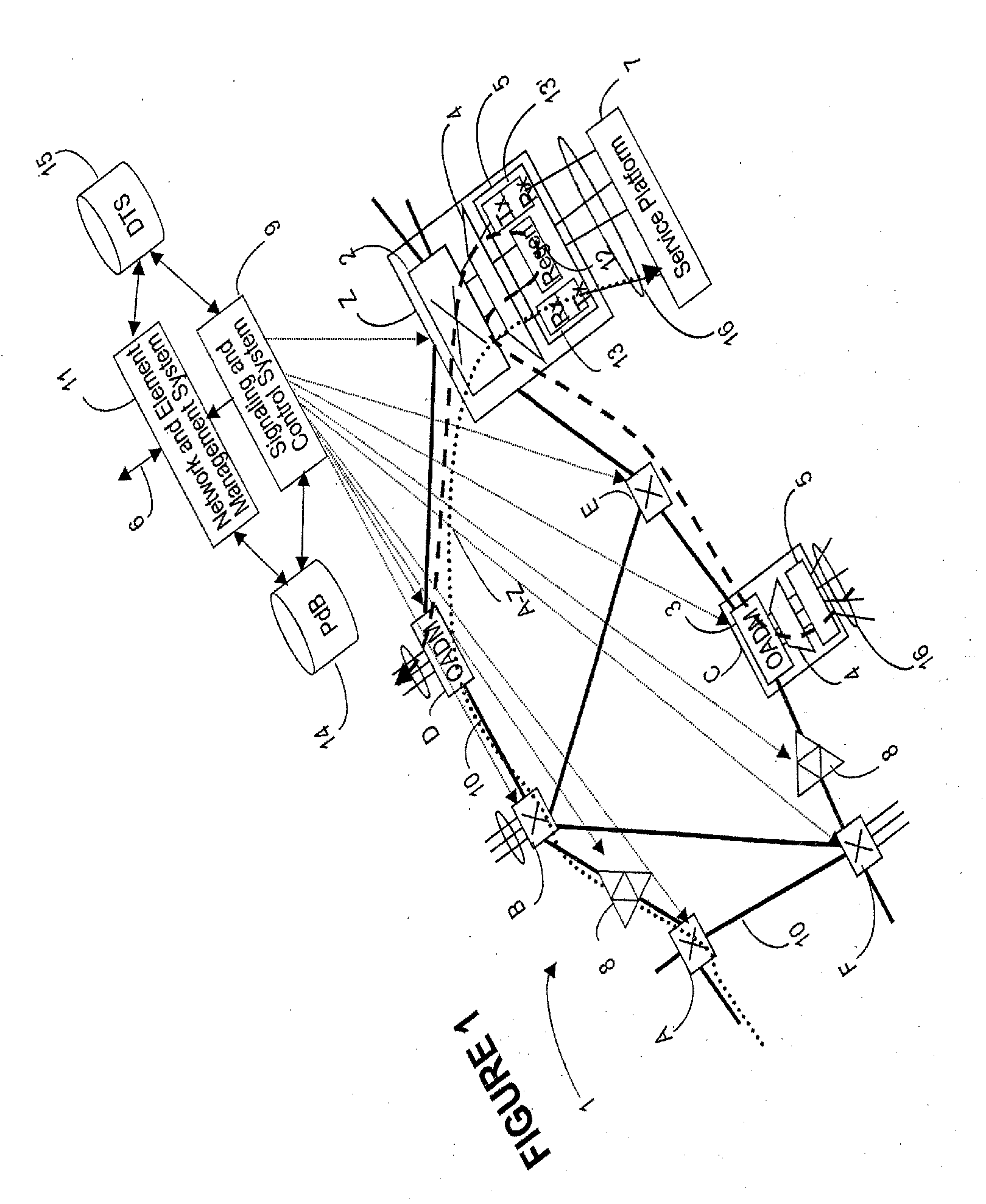
[0028]An example of a wavelength switched optical network (or automatically switched network, or agile network) is shown in FIG. 1. The DWDM layer of network 1 is mesh-connected with wavelength switching nodes (also called flexibility points or flexibility sites) instead of traditional pt-pt nodes. Connections are set-up and removed on request with optimal use of optical-to-electrical-to-optical (OEO) conversion. The architecture and operation of this network is described in the above-referenced co-pending patent application Ser. No. 09 / 876,391, which is incorporated herein by reference.

[0029]To summarize, network 1 comprises bidirectional fiber links 10 connecting a plurality of nodes, which are nodes A, B, C, D, E, F, Z in the example of FIG. 1. These nodes may be switching nodes A, B, E, F, Z, or OADM (optical add / drop multiplexing) nodes C, D. Local traffic 16 originating and terminating on a service platform 7 (a router, an ATM switch, an EXC, etc.) accesses the network 1 at a ...


PUM


Abstract

The method of placing regenerators along a trail connecting a source network node with a destination network node of an automatically switched optical network first identifies N tentative regeneration sites and n+1 optical paths along the trail. Wavelengths are assigned to each optical path, and the performance of the trail is assessed based on regenerator placement data and wavelength assignment data.

Description

PRIORITY PATENT APPLICATION[0001]This patent application is a continuation in part of the co-pending U.S. patent application Ser. No. 09 / 909,265, entitled “Wavelength Routing and Switching Mechanism for a Photonic Transport Network”, Smith et al., filed Jul. 19, 2001, assigned to Innovance Networks, docket 1021.RELATED US PATENT APPLICATIONS[0002]U.S. patent application “Architecture For A Photonic Transport Network”, (Roorda et al.), Ser. No. 09 / 876,391, filed Jun. 7, 2001, assigned to Innovance Networks, docket 1001.[0003]U.S. patent application “Wavelengths assignment in an optical WDM network”, (Solheim et al.), SN Not available yet, filed Dec. 12, 2001) assigned to Innovance Networks, docket 1011.FIELD OF THE INVENTION[0004]The invention is directed to a telecommunication network, and in particular to a system and method for placing regenerators along a route of a wavelength switched optical network.BACKGROUND OF THE INVENTION[0005]The most relevant trends in the optical networ...

Claims


Application Information

Patent Timeline
Patent Type & Authority Applications(United States)
IPC IPC(8): H04Q11/00
CPCH04Q11/0005H04J14/0221H04J14/0227H04J14/0246H04J14/0283H04J14/0284H04J14/0257H04J14/0267H04J14/0268H04J14/0269
Inventor RIDER, DOUGLAS CLAYTONSLEZAK, JAMES CRAIGSMITH, ANTHONY VEMON WALKER
Owner LUCENT TECH INC
Why Eureka
Try Eureka