
Dynamic Assignment Of Wavelengths In Agile Photonic Networks

a photonic network and dynamic assignment technology, applied in the field of agile photonic networks, can solve the problems of complex assignment of wavelengths, reduced network cost, and inability to fully exploit the advantages of ulr, and achieve the effects of reducing time-to-bandwidth (ttb), reducing the complexity of nodes, and reducing network costs

Inactive Publication Date: 2013-11-14
ALCATEL LUCENT SAS
View PDF4 Cites 3 Cited by
  • Summary
  • Abstract
  • Description
  • Claims
  • Application Information

AI Technical Summary

Benefits of technology

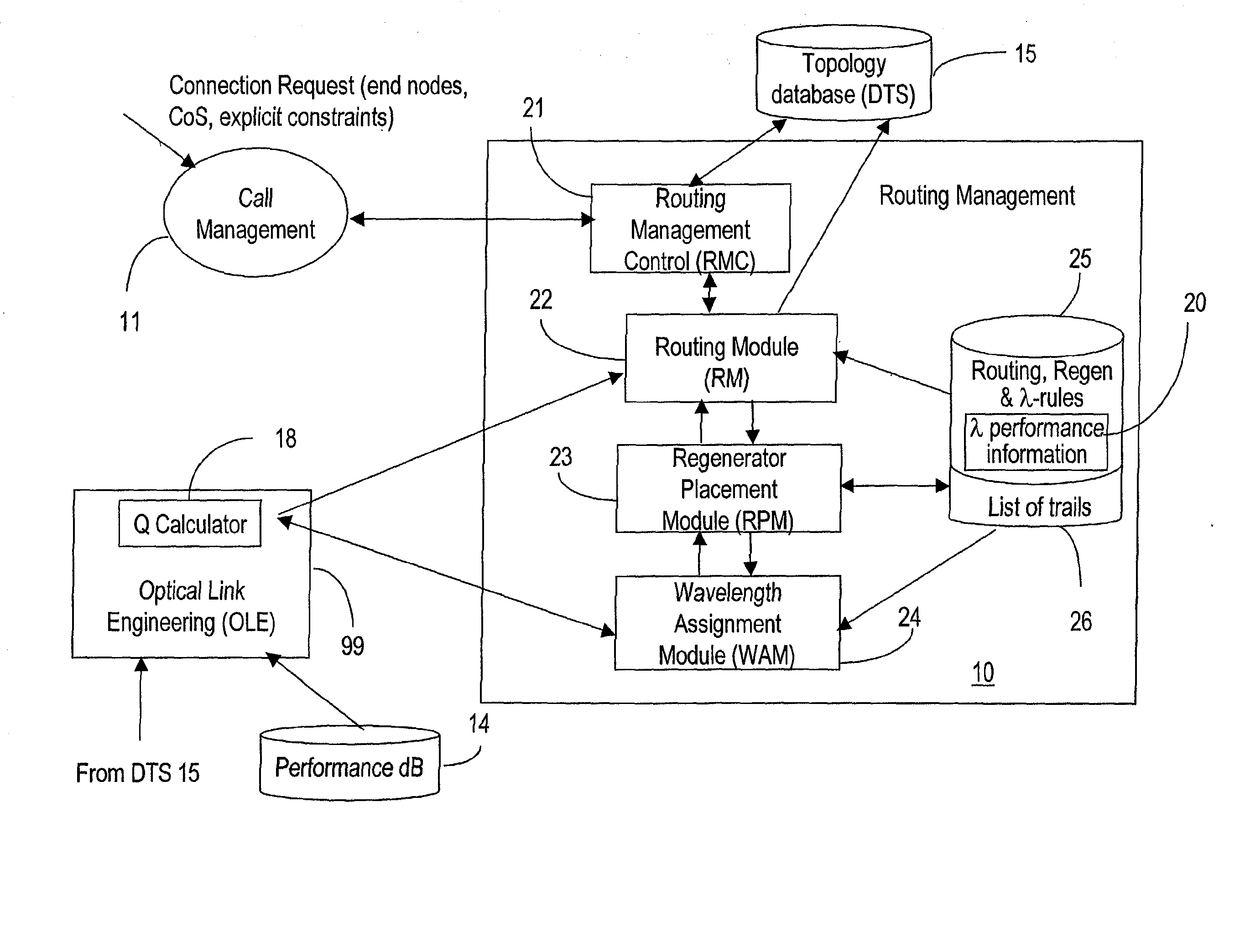
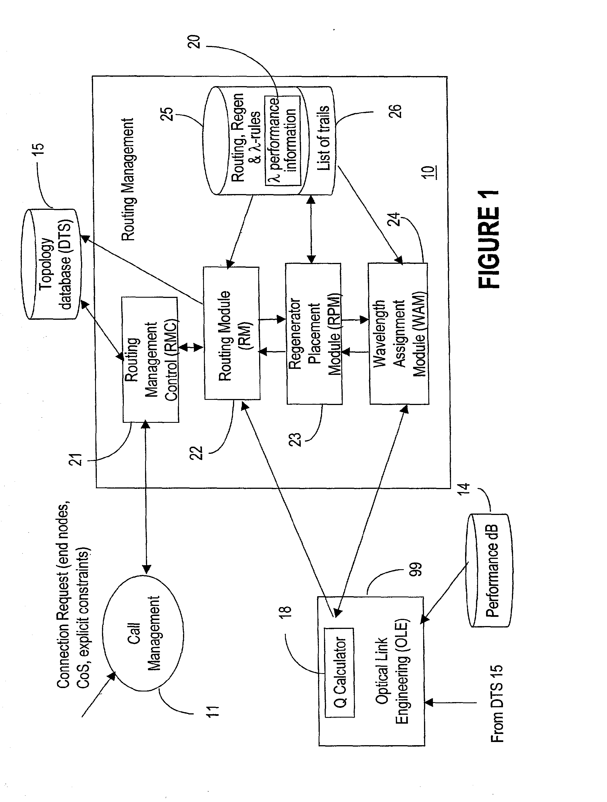
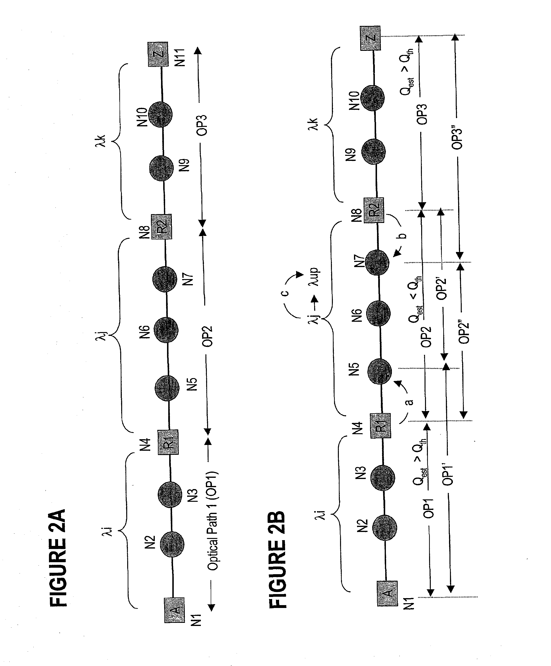
The invention is a mechanism for automatically assigning wavelengths to optical paths based on network architecture, connectivity, and loading conditions. This mechanism uses searching techniques with various degrees of sophistication to find an appropriate wavelength-path match. The selection of wavelengths for each optical path is performed with optimal use of network resources, while ensuring that the quality of the selected trail is adequate for the respective call. The "technical effects" of this mechanism include reducing time-to-bandwidth, reducing network resource utilization, increasing quality-of-service, and contributing to network service costs reduction.

Problems solved by technology

In this architecture, the advantages of the ULR cannot be fully exploited.
This approach dramatically reduces the node complexity, and consequently the network cost.
Nonetheless, the selection and assignment of the right wavelength for each optical path for the best possible utilization of available wavelengths is a complex problem.

Method used


Image

  • Dynamic Assignment Of Wavelengths In Agile Photonic Networks
  • Dynamic Assignment Of Wavelengths In Agile Photonic Networks
  • Dynamic Assignment Of Wavelengths In Agile Photonic Networks

Examples


Embodiment Construction

[0035]The following description is of a preferred embodiment by way of example only and without limitation to combination of features necessary for carrying the invention into effect.

[0036]The following definitions are used throughout this specification: “Dial”, “Redial”, “Call” or “connection request” refers to a request for exchanging traffic between two nodes. It includes conditions such as the source and destination nodes, traffic bandwidth and rate, the class of service CoS, the type of routing, explicit constraints, etc.

[0037]“Photonic network” is a network where an end-to-end connection is established along a trail whereby the traffic may be automatically switched at all or some intermediate nodes in optical format. The nodes of a photonic network could be optical add / drop multiplexing (OADM) nodes that provide add, drop and optical passthrough, or could be optical cross-connect nodes that provide add, drop and optical switching of the passthrough traffic.

[0038]A “connection”...


PUM


Abstract

In an automatically switched optical network, the wavelengths are assigned to optical path based on their intrinsic physical performance and on the current network operating parameters. The wavelength performance information is organized in binning tables, based primarily on the wavelength reach capabilities. A network topology database provides the distance between the nodes of the network, which is used to determine the length of the optical path. Other network operating parameters needed for wavelength selection are also available in this database. Once a bin corresponding to the path length is identified in the binning table, the wavelength for that path is selected based on length only, or based on the length and one or more additional parameters. The optical path performance is estimated for the selected wavelength, and the search continues if the estimated path performance is not satisfactory. Several available wavelengths are searched and of those, the wavelength that is most used along the optical path in consideration or alternatively network-wide is selected and assigned. This method helps minimize wavelength fragmentation. The binning tables may have various granularities, and may be organized by reach, or by reach, wavelength spacing, the load on the respective optical path, the fiber type, etc.

Description

PRIORITY PATENT APPLICATION[0001]This patent application is a continuation in part of the co-pending U.S. patent application Ser. No. 09 / 909,265, entitled “Wavelength Routing and Switching Mechanism for a Photonic Transport Network”, Smith et al., filed Jul. 19, 2001, assigned to Innovance Networks, docket 1021.RELATED U.S. PATENT APPLICATION[0002]U.S. Patent Application “Wavelengths assignment in an optical WDM network”, (Solheim et al.), Ser. No. Not available yet, filed Dec. 12, 2001 assigned to Innovance Networks, docket 1011.[0003]U.S. Patent Application “Regenerator Placement Mechanism For Wavelength Switched Optical Networks” (Rider et al.), Ser. No. not available yet, filed Mar. 13, 2002 and assigned to Innovance Networks, docket 1045.FIELD OF INVENTION[0004]The invention is directed to an agile photonic network (also known as automatically switched optical network ASON, or as all optical network), and in particular to a system and method for assigning wavelengths to a conne...

Claims


Application Information

Patent Timeline
Patent Type & Authority Applications(United States)
IPC IPC(8): H04Q11/00
CPCH04J14/0246H04J14/0221H04J14/0283H04Q11/0005H04J14/0257H04J14/0267H04J14/0269H04J14/0284H04J14/02214
Inventor SRIRAM, KOTIKALAPUDIKATIYAR, MUKULTITCHENER, JONATHANNEDNUR, RAJENDER RAOSMITH, ANTHONY VERNON WALKER
Owner ALCATEL LUCENT SAS
Learn More