Trail engineering in agile photonic networks

a photonic network and trail technology, applied in the field of telecommunication networks, can solve the problems of complex network engineering and planning, scaling-up and/or providing new services in the point-to-point network, and requiring extensive simulation and testing, and achieves the effects of convenient and fast network engineering, convenient selection of trails, and convenient operation

Active Publication Date: 2006-01-05
ALCATEL-LUCENT USA INC +1
View PDF5 Cites 26 Cited by
  • Summary
  • Abstract
  • Description
  • Claims
  • Application Information

AI Technical Summary

Benefits of technology

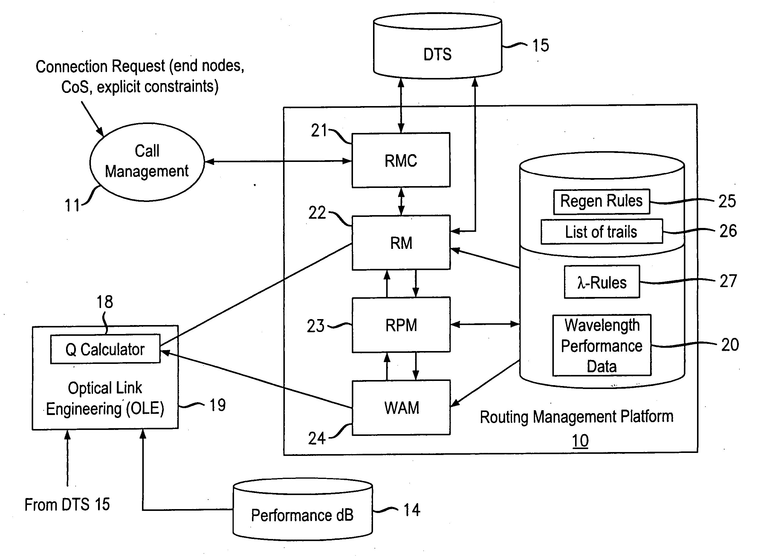
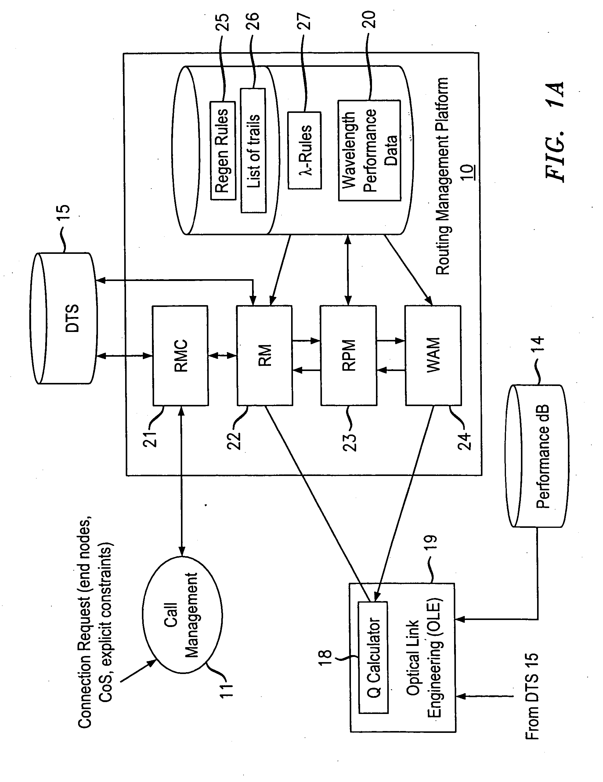
[0013] According to the principles of the invention, an agile transparent network is provided with a trail routing and switching (also called “engineering”) mechanism that enables efficient use of regenerators and wavelengths available in the network, while maintaining a very efficient time-to-service.
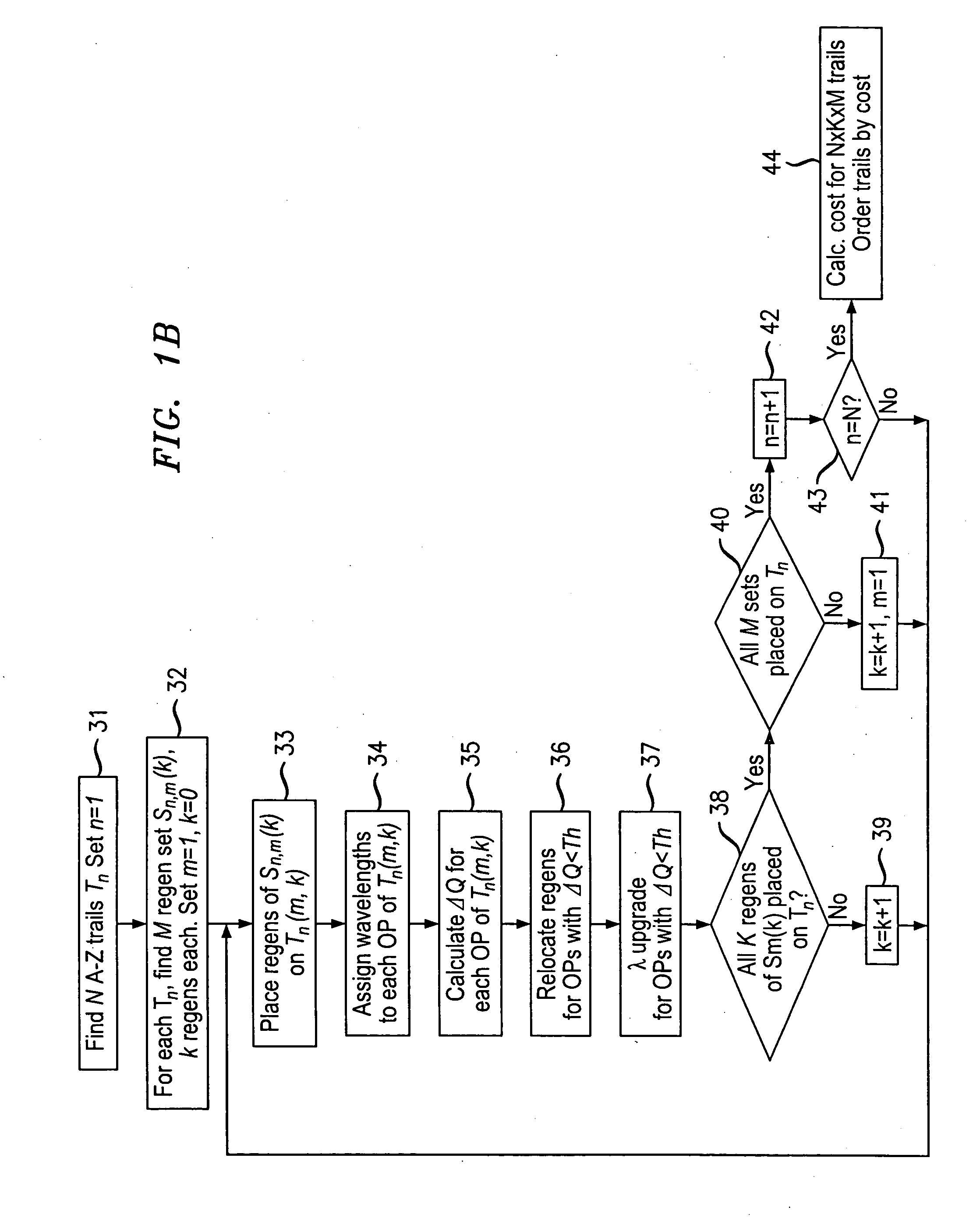
[0014] Advantageously, the trail engineering mechanism according to the invention allows fast, automatic establishment of new connections based on the current network architecture, connectivity and loading and also on conditions in the connection request. Selection of regenerator sites and of the wavelengths used on each regenerator segment is performed with optimal use of current network resources, while ensuring that the quality of the selected trail is adequate for the respective call. The mechanism provides for both distance and performance balancing, and it optimizes network response time.

Problems solved by technology

In addition, the point-to-point network requires duplication of equipment for protection / restoration in case of faults.
As a result, the configuration of a typical node of a point-to-point network is very complex.
Furthermore, scaling-up and / or providing new services in a point-to-point network requires very complex network engineering and planning involving extensive simulation and testing.
Nonetheless, selection and assignment of the correct wavelength for each optical path for the best possible utilization of available wavelengths is a complex problem.

Method used


Image

  • Trail engineering in agile photonic networks
  • Trail engineering in agile photonic networks
  • Trail engineering in agile photonic networks

Examples


examples

[0111]FIG. 4A shows a heterogeneous trail with nine nodes, L=5352 km, and with the four fiber types SMF, DCF, TWC and LEAF. This trails is used together with FIGS. 3B and 3C for illustrating an example of an initial regenerator placement. Since in this scenario the best fiber type LEAF has the Max_Reach of 4,500 km, there is at least one regenerator needed. Lave for this trail is 5352 / 2=2676 km, considering d=1. As before, let's assume that the initial threshold is 0.3 dB, the assignment threshold is 0.0 dB, and the increment (used later) is 0.4 dB.

[0112] Initially, the regenerator is placed at node N6, since Σ(Σ=L1+L2 L3+L4+L5=2,852 km), is first greater than Lave at node N6, resulting in a first optical path OP1 between nodes N1 and N6 (L1=2,852 km) and a second optical path OP2 between nodes N6 and N9 (L2=2,500 km).

[0113] The trail construction starts with WAM 24 checking for a continuous wavelength for OP1. Let's assume that a continuous wavelength is available in all bins. Th...


PUM


Abstract

An agile transparent network with a trail routing and switching (also called “engineering”) mechanism is provided that enables efficient use of regenerators and wavelengths available in the network, while maintaining a very efficient time-to-service. The trail engineering mechanism allows fast, automatic establishment of new connections based on the current network architecture, connectivity and loading and also on conditions in the connection request. Selection of regenerator sites and of the wavelengths used on each regenerator segment is performed with optimal use of current network resources, while ensuring that the quality of the selected trail is adequate for the respective call. The mechanism provides for both distance and performance balancing, and it optimizes the network response time.

Description

CROSS-REFERENCE TO RELATED APPLICATIONS [0001] This patent application is a continuation-in-part of co-pending U.S. patent application Ser. No. 10 / 128,092, entitled “Dynamic Assignment of Wavelengths in Agile Photonic Networks” and filed Apr. 23, 2002, which is a continuation-in-part of co-pending U.S. patent application Ser. No. 09 / 909,265, entitled “Wavelength Routing and Switching Mechanism for a Photonic Transport Network” and filed Jul. 19, 2001. [0002] This patent application is also related to co-pending U.S. patent application Ser. No. 10 / 097,901, entitled “Regenerator Placement Mechanism for Wavelength Switched Optical Networks” and filed Mar. 13, 2002 and also co-pending U.S. patent application Ser. No. 10 / 391,863, entitled “Channel Wavelength Assignment With Transient Reduction” and filed Mar. 19, 2003, both of which are incorporated herein by reference in their entirety.TECHNICAL FIELD [0003] The invention is directed to a telecommunication network and, in particular, to...

Claims


Application Information

Patent Timeline
Patent Type & Authority Applications(United States)
IPC IPC(8): H04B10/02
CPCH04J14/0227H04J14/0241H04J14/0284
Inventor GUY, JOHN PETERKATIYAR, MUKULNADON, ROBERT ALAINNEDNUR, RAJENDER RAOSCHEERER, CHRISTIANTITCHENER, JONATHAN
Owner ALCATEL-LUCENT USA INC
Why Eureka
Try Eureka