
Regenerators placement mechanism for wavelength switched optical networks

Inactive Publication Date: 2013-10-29
ALCATEL LUCENT SAS
View PDF4 Cites 18 Cited by
  • Summary
  • Abstract
  • Description
  • Claims
  • Application Information

AI Technical Summary

Benefits of technology

The invention relates to a method for optimizing the placement of regenerators and assignment of wavelengths in a network to improve the efficient use of resources and minimize the time taken to establish new connections. The method takes into account the network architecture, connectivity, and load, as well as the conditions in the connection request, to select the most suitable regenerators and wavelengths for each segment. It ensures that the selected path is suitable for the call while balancing distance and performance. The invention optimizes network response time and reduces the time to service.

Problems solved by technology

In addition, the pt-pt network requires duplication of equipment for protection / restoration in case of fault.
As a result, the configuration of a typical node of a point-to-point network is very complex.
Furthermore, scaling-up or / and providing new services in a point-to-point network requires very complex network engineering and planning involving extensive simulation and testing.

Method used


Image

  • Regenerators placement mechanism for wavelength switched optical networks
  • Regenerators placement mechanism for wavelength switched optical networks
  • Regenerators placement mechanism for wavelength switched optical networks

Examples


Embodiment Construction

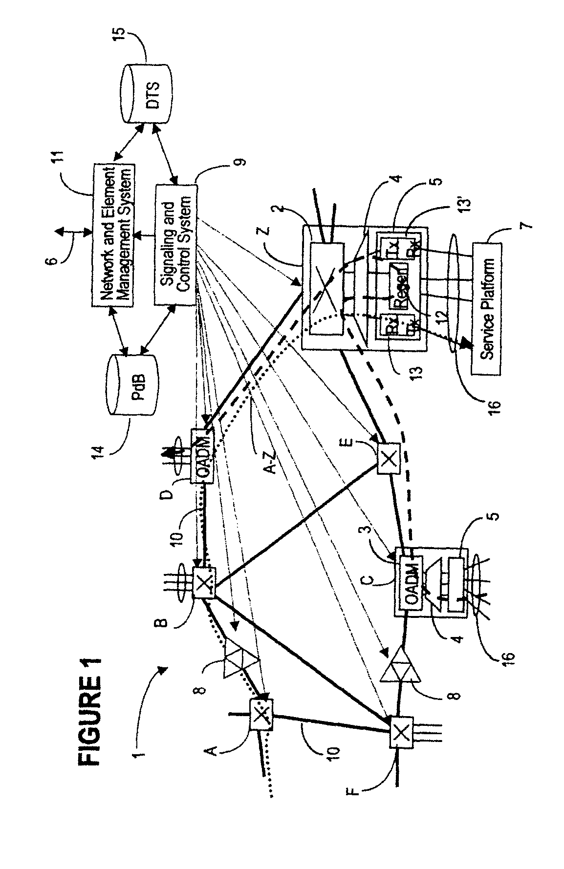
[0028]An example of a wavelength switched optical network (or automatically switched network, or agile network) is shown in FIG. 1. The DWDM layer of network 1 is mesh-connected with wavelength switching nodes (also called flexibility points or flexibility sites) instead of traditional pt-pt nodes. Connections are set-up and removed on request with optimal use of optical-to-electrical-to-optical (OEO) conversion. The architecture and operation of this network is described in the above-referenced co-pending patent application Ser. No. 09 / 876,391, which is incorporated herein by reference.

[0029]To summarize, network 1 comprises bidirectional fiber links 10 connecting a plurality of nodes, which are nodes A, B, C, D, E, F, Z in the example of FIG. 1. These nodes may be switching nodes A, B, E, F, Z, or OADM (optical add / drop multiplexing) nodes C, D. Local traffic 16 originating and terminating on a service platform 7 (a router, an ATM switch, an EXC, etc.) accesses the network 1 at a ...


PUM


Abstract

The method of placing regenerators along a trail connecting a source network node with a destination network node of an automatically switched optical network first identifies N tentative regeneration sites and n+1 optical paths along the trail. Wavelengths are assigned to each optical path; and the performance of the trail is assessed based on regenerator placement data and wavelength assignment data. The data identifying this regenerator path, namely regenerator placement data, the wavelength assignment data and the performance parameter of the trail are stored in a list, if the performance parameter is over a threshold. Selection of the tentative sites is revised whenever the initial placement fails due to a reach problem, a wavelength-blocking problem or a path quality problem. If the time for revising the initial placement, or the cost of a regenerator path is unacceptable, the regenerator path is abandoned and a further placement is initiated. Next, a further regenerator placement is attempted for the same trail using n+1 regenerators, and the further regenerator path is stored in the list, etc. Still further, regenerator placement is attempted for another trail, and so on, until a specified number of regenerator paths are stored in the list.

Description

PRIORITY PATENT APPLICATION[0001]This patent application is a continuation in part of the co-pending U.S. patent application Ser. No. 09 / 909,265, entitled “Wavelength Routing and Switching Mechanism for a Photonic Transport Network”, Smith et al., filed Jul. 19, 2001, assigned to Innovance Networks.RELATED US PATENT APPLICATIONS[0002]U.S. Patent Application “Architecture For A Photonic Transport Network”, (Roorda et al.), Ser. No. 09 / 876,391, filed Jun. 7, 2001, assigned to Innovance Networks.[0003]U.S. Patent Application “Wavelengths assignment in an optical WDM network”, (Solheim et al.), Ser. No. 10 / 017,833, filed Dec. 12, 2001) assigned to Innovance Networks.FIELD OF THE INVENTION[0004]The invention is directed to a telecommunication network, and in particular to a system and method for placing regenerators along a route of a wavelength switched optical network.BACKGROUND OF THE INVENTION[0005]The most relevant trends in the optical networking area are the increase in the networ...

Claims


Application Information

Patent Timeline
IPC IPC(8): H04B10/29
CPCH04J14/0257H04J14/0267H04J14/0268H04J14/0269H04J14/0227H04J14/0246H04J14/0283H04J14/0284H04Q11/0005H04J14/0221
Inventor RIDER, DOUGLAS CLAYTONSLEZAK, JAMES CRAIGWALKER SMITH, ANTHONY VERNON
Owner ALCATEL LUCENT SAS
Learn More