Method for generating a synthetic perspective image

a synthetic perspective and image technology, applied in the field of synthetic perspective image generation, can solve the problems of high accuracy of the on-board sensor, difficult and expensive, and difficulty in registering the sensor image with the reference image, etc., to achieve sufficient speed, adequate quality and accuracy, and avoid computational difficulty

a synthetic perspective and image technology, applied in the field of synthetic perspective image generation, can solve the problems of high accuracy of the on-board sensor, difficult and expensive, and difficulty in registering the sensor image with the reference image, etc., to achieve sufficient speed, adequate quality and accuracy, and avoid computational difficulty

US7580591B2Active Publication Date: 2009-08-25THE BOEING CO

Image

  • Method for generating a synthetic perspective image
  • Method for generating a synthetic perspective image
  • Method for generating a synthetic perspective image

Examples


Embodiment Construction

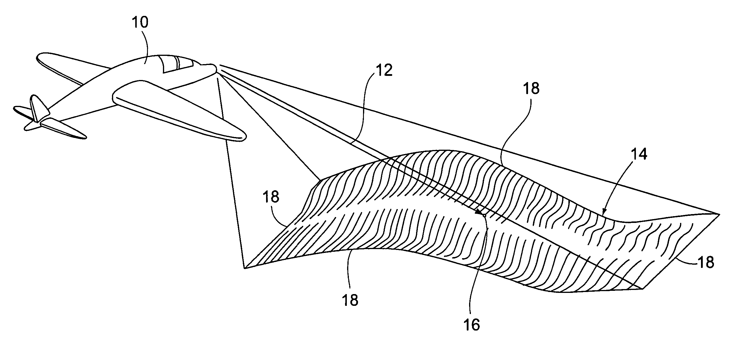
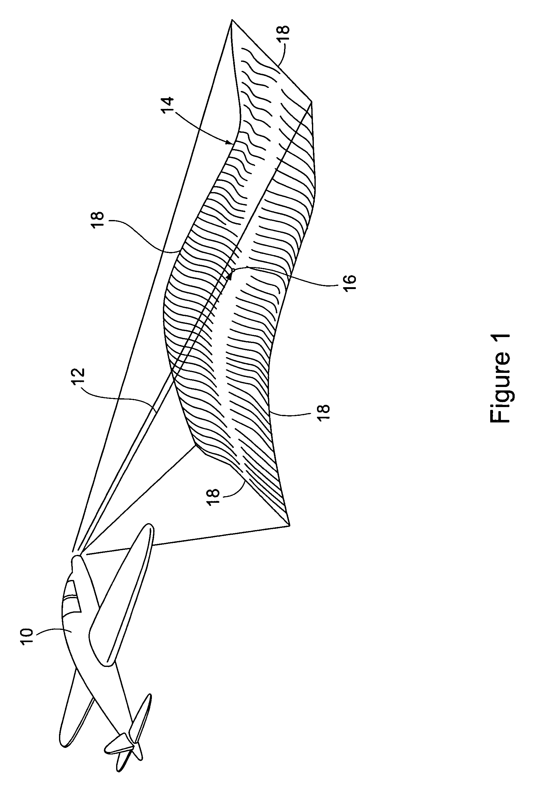
[0039]As stated earlier, the present invention provides a method of generating a synthetic perspective image of a location from a reference image of the location, where the generated perspective image is displayed on a typical display screen comprised of rows and columns of pixels, and recorded as a numerical array of electronically stored values for additional processing, or for storage in a computer file for later use. The description of the method to follow is made with reference to its use in a military aircraft, where the method generates and displays a synthetic perspective image of a geographic target area. However, it should be understood that the method of the invention has many different applications, for example, for generating a synthetic perspective image of a location to be used by a robot to enable movement of the robot around obstacles at the given location. In another example, the method of the invention may be employed in generating a synthetic perspective image of...


PUM


Abstract

A method of generating a synthetic perspective image that matches the viewing perspective and internal geometry of a known image sensor, for example, a forward-looking infrared sensor or a synthetic aperture radar sensor, without using specialized hardware and without the computational difficulty inherent in standard image generating means is provided. The synthetic perspective image is generated in a forward mapping process, which solves the problems of complete mapping of the perspective image and of hidden surfaces, in a manner that provides sufficient speed and adequate quality or accuracy for standard reference images to be used in registering with the sensor images.

Description

BACKGROUND OF THE INVENTION[0001](1) Field of the Invention[0002]The present invention pertains to a method of generating a synthetic perspective image of a location, to closely match the appearance of an electronically sensed image of the location. The synthetic perspective image is constructed from a corresponding database stored reference image of the location, and a corresponding database stored reference digital elevation model of the location. The reference image is comprised of rows and columns of pixels to which elevation values obtained from the digital elevation model have been associated, and the reference image pixels are each mapped to pixels of a synthetic perspective image display.[0003](2) Description of the Related Art[0004]Modern military aircraft require a capability to target, from the aircraft cockpit, precision-guided weapons. One method to do this is to use sensor images obtained by sensors carried on the aircraft. However, making an on-board sensor highly acc...

Claims


Application Information

Patent Timeline
25 Aug 2009
Publication
US7580591B2
IPC
G06K9/32
CPC
G06T17/05; G06T15/20
Inventors
OLDROYD, LAWRENCE A.