
Image forming apparatus and image formation control method thereof

a technology of image forming and control method, which is applied in the direction of electrographic process apparatus, optics, instruments, etc., can solve the problems of insufficient achievement of the purpose of variable data printing, color and common image color not matching at each copy of the print product, etc., and achieves the effect of reducing productivity, density and color, and adequate image quality

Inactive Publication Date: 2008-03-27
CANON KK
View PDF5 Cites 3 Cited by
  • Summary
  • Abstract
  • Description
  • Claims
  • Application Information

AI Technical Summary

Benefits of technology

[0013]The present invention provides an image forming apparatus and an image formation control method thereof that can realize an image having adequate image quality, density and color, without provoking excessive consumption of a developer and reduction in productivity.
[0015]According to the present invention, an image having the adequate image quality, density and color can be realized according to the purpose of a print product, without provoking excessive consumption of a developer and reduction in productivity, even in an image forming apparatus having large fluctuations in a printing rate.

Problems solved by technology

In particular, when individual image formation is performed in response to the demand of a client, such as in the above variable data printing, since the printing rate is extremely different from one copy of a print product to another, a problem arises that a common image color does not match at each copy of the print product, or the image color does not match for a predetermined portion.
Therefore, there is a problem that a good image with matching color cannot be provided to each client, and the purpose of the variable data printing cannot be achieved sufficiently.
However, when the image density is frequently adjusted, problems arise that a developer for adjusting the image density is excessively consumed, and productivity is reduced.
In addition, the excessively consuming the developer causes the problem to worsen when a print product in which a shift in color does not pose much of a problem is formed, for example, even when an image is formed for flyers for simple distribution, excessive adjustment of image density is executed.
As a result, there is a problem that it is impossible to stabilize the color of the image in a predetermined range.

Method used


Image

  • Image forming apparatus and image formation control method thereof
  • Image forming apparatus and image formation control method thereof
  • Image forming apparatus and image formation control method thereof

Examples


first embodiment

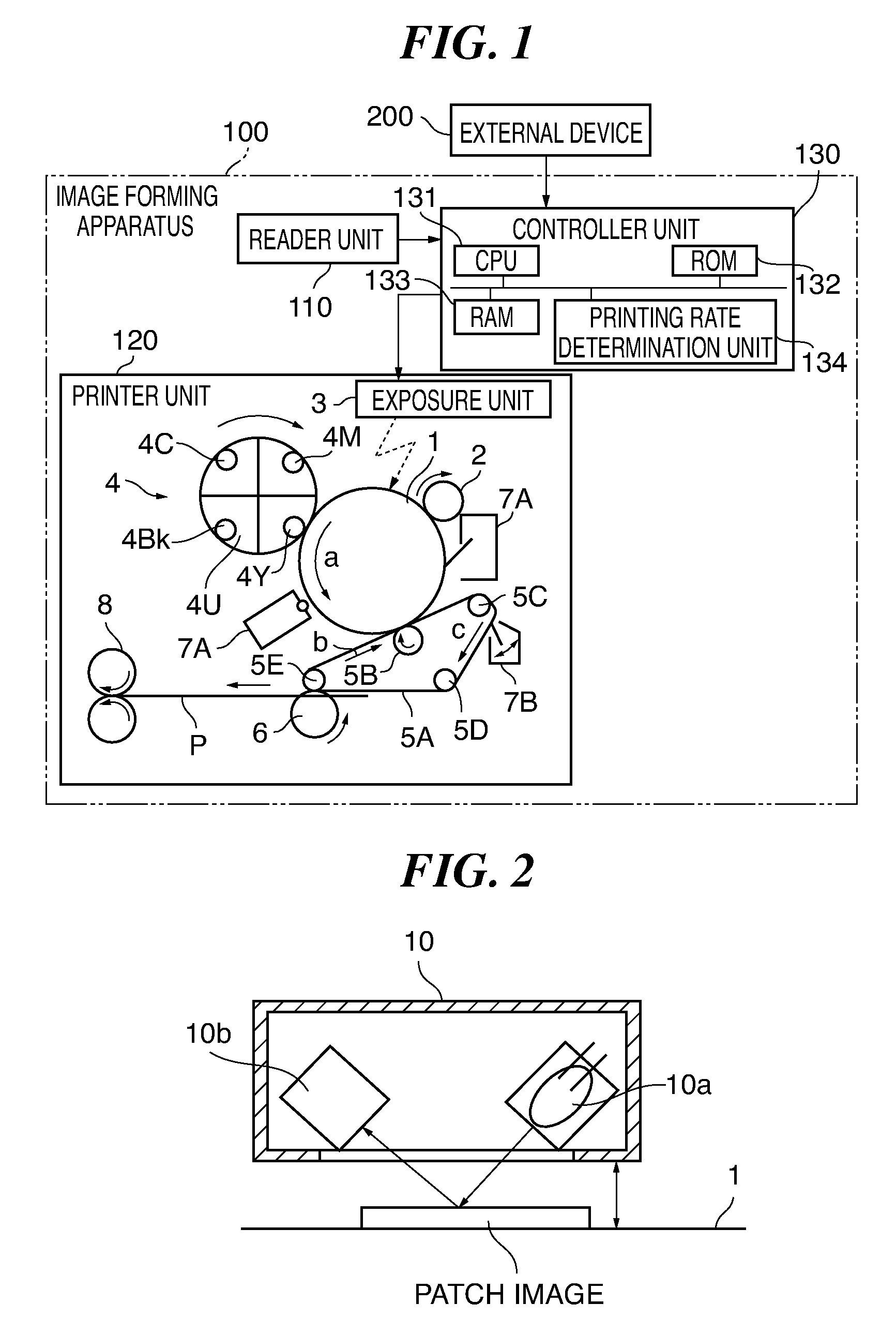
[0041]FIG. 1 is a diagram showing the configuration of the essential parts of an image forming apparatus according to a first embodiment of the present invention.

[0042]In FIG. 1, an image forming apparatus 100 according to the present embodiment is constituted as a full-color electrophotographic image forming apparatus comprising a reader unit 110, a printer unit 120, a controller unit 130 and an operation unit (not shown). In addition, the image forming apparatus 100 can receive image information sent from an external device 200 such as a PC. Note that, in the present embodiment, the image forming apparatus 100 is a copying machine (complex machine) that reads and forms an image, but without limiting thereto, the device may be a printer that performs only image formation.

[0043]The reader unit 110 reads an image from an original document and outputs image information to the controller unit 130. The printer unit 120 comprises a photoconductive drum 1, a charger roller 2, an exposure ...

second embodiment

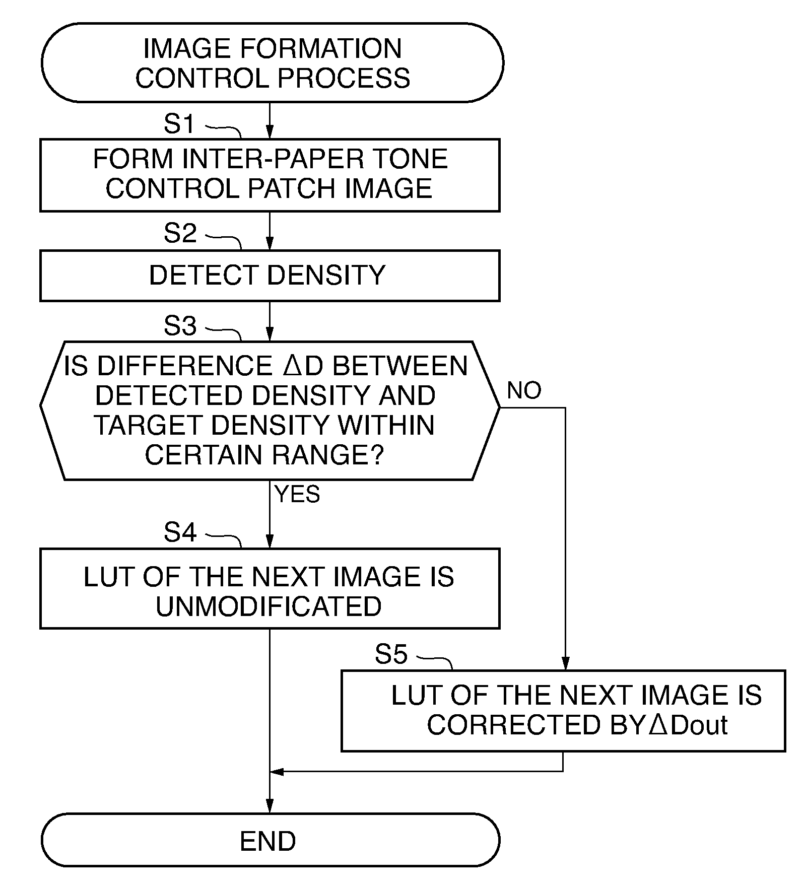
[0104]The second embodiment of the present invention is different from the above first embodiment in that inter-paper tone control shown in FIG. 11 described later is executed. Therefore, identical sections are designated by the same reference numerals shown in FIGS. 1 and 2, while omitting description thereof.

[0105]In the above first embodiment, in order to respond wide range of print products, the configuration is such that the frequency of the inter-paper tone control varies uniformly and similarly according to the printing rate. However, for example, when flyers or the like are printed, which do not really require a high-quality image, the frequency of the inter-paper tone control becomes excessive, resulting in an increase of print cost per sheet due to excessive consumption of developers for inter-paper tone control. On the other hand, for example, when luxury catalogs or the like are printed, which require higher quality image, further stabilization of density / color fluctuati...

third embodiment

[0113]The third embodiment of the present invention is different from the above first and second embodiments in that inter-paper tone control shown in FIG. 12 described later is executed. Therefore, identical sections are designated by the same reference numerals shown in FIGS. 1 and 2, while omitting description thereof.

[0114]In the above second embodiment, the configuration is such that the frequency of the inter-paper tone control varies according to the quality (“normal quality”, “cost priority quality” and “high-end quality”) of an image selected from the operation unit.

[0115]As compared thereto, in the present embodiment, from the operation unit (not shown) of an image forming apparatus 100″, a user can select an image formation mode (text / photographic mode, text mode). This allows the frequency of the inter-paper tone control in an image forming job to be changed according to the image formation mode selected from the operation unit, as shown in FIG. 12 described later.

[0116]...


PUM


Abstract

An image forming apparatus that can realize an image having adequate image quality, density and color, without provoking excessive consumption of a developer and reduction in productivity. Image formation is performed by forming a latent image on an image carrier based on image information, then developing and transferring the latent image. An image for adjustment on a portion is formed other than a portion on which the latent image is formed on the image carrier. The density of the image for adjustment is detected. Image density is adjusted based on the density of the detected image for adjustment. Image formation control is executed whereby density is adjusted when an image is formed. A printing rate that indicates the percentage of the image formation to a sheet used for image formation is calculated. When the printing rate is determined to be within a set range, the image formation control is executed at a set frequency. On the other hand, when the printing rate is determined to be outside the set range, the set frequency is changed and the image formation control is executed.

Description

BACKGROUND OF THE INVENTION[0001]1. Field of the Invention[0002]The present invention relates to an image forming apparatus and an image formation control method thereof, which are applied to improve image quality when electrophotographic image formation is performed.[0003]2. Description of the Related Art[0004]Conventionally, an image forming apparatus comprises an image adjustment function that all the adjustment process is operated in the device in order to suppress changes in color concomitantly to a change in environment or a change over time, and changes in color after replacement of each part due to consumption and various types of maintenance work (see e.g. Japanese Laid-Open Patent Publication (Kokai) No. H09-319270 and Japanese Laid-Open Patent Publication (Kokai) No. H09-326926).[0005]The above related art has executed the following control. The control includes maximum density (Dmax) control, tone (half tone) control, detection of life duration of various parts, and tone...

Claims


Application Information

Patent Timeline
Patent Type & Authority Applications(United States)
IPC IPC(8): G03G15/01
CPCG03G2215/00042G03G15/5041G03G2215/0177G03G2215/0164
Inventor YAMAMOTO, TAKEOHATA, SHIGEONAGATA, NAOHISAOTA, MITSUHIROKAMIYA, DAISAKU
Owner CANON KK
Learn More