
Cartridge

a technology of process cartridges and grips, applied in the field of process cartridges, can solve the problems of not being able to make the grip member thick enough, affecting usability, and difficult to mold into a desired shape of the grip member, etc., and achieve the effect of improving the strength of the grip member

Inactive Publication Date: 2014-03-27
CANON KK
View PDF6 Cites 7 Cited by
  • Summary
  • Abstract
  • Description
  • Claims
  • Application Information

AI Technical Summary

Benefits of technology

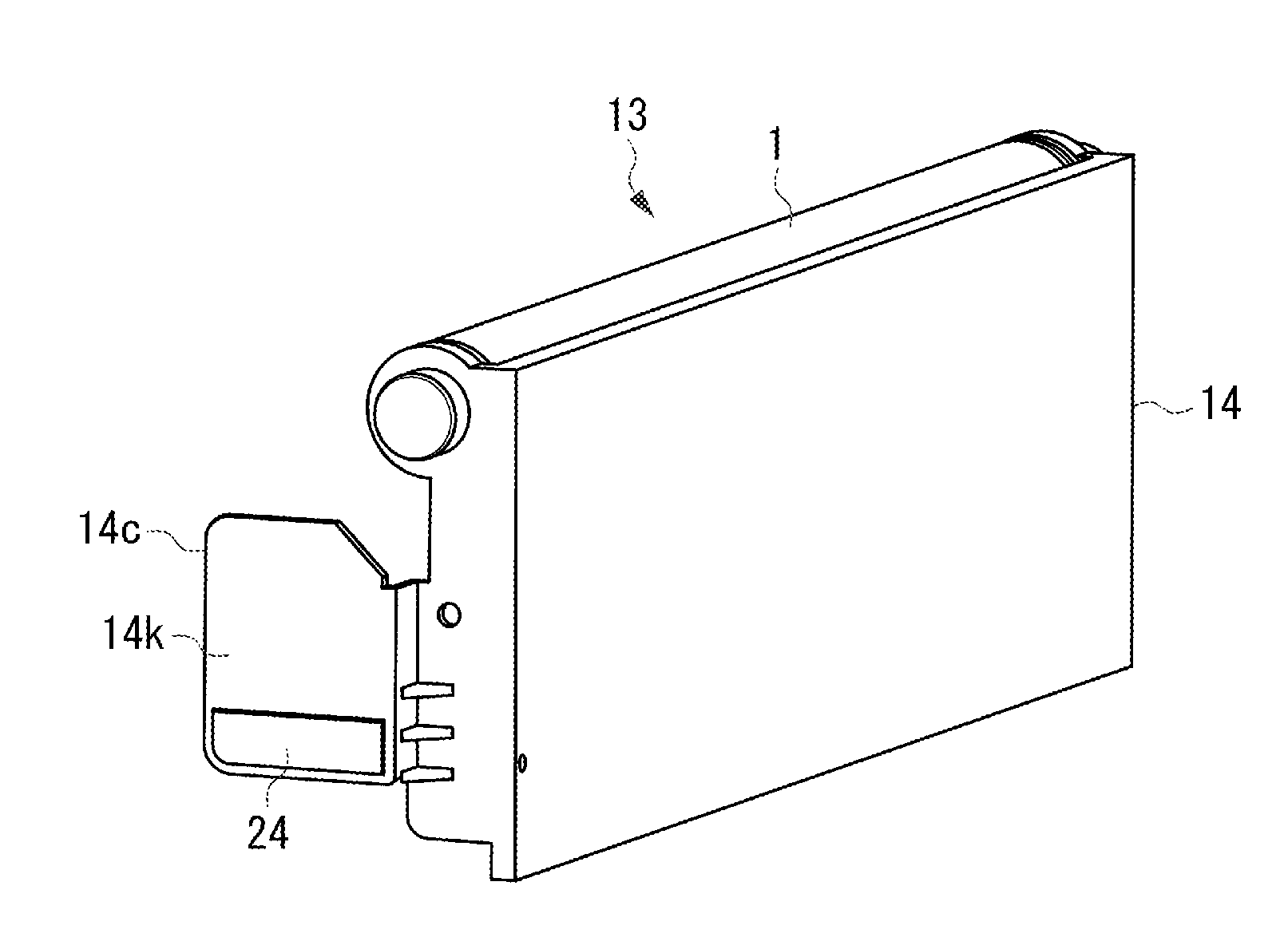
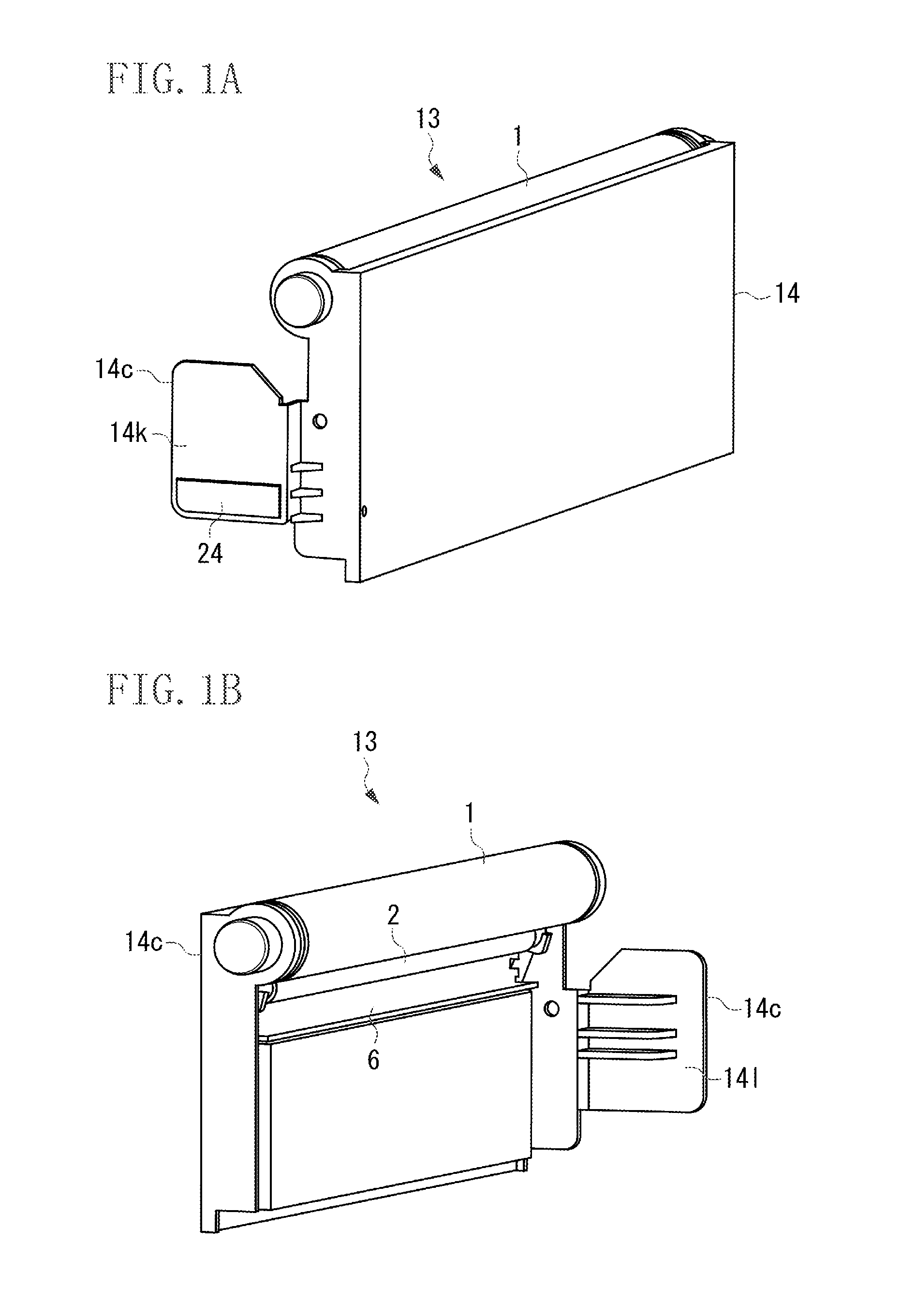
The present patent is about a cartridge that can strengthen the grip on a frame when it is attached to an image forming apparatus. The cartridge has a frame made of a first type of plastic and a grip made of a second type of plastic that is integrally molded onto the frame. The second molded member is thicker than the first molded member, making the grip easier to hold and use when mounting or dismounting the cartridge.

Problems solved by technology

This is because a grip member having a greater thickness is more difficult to mold into a desired shape due to the occurrence of sink marks.
However, depending on the design of the process cartridge, it may not be possible to make the grip member thick enough.
In such a case, there may be an adverse impact on usability due to flexing in the grip member as a result of the load applied during the mounting / removal operation.

Method used


Image

  • Cartridge
  • Cartridge
  • Cartridge

Examples


Embodiment Construction

[0022]Various exemplary embodiments, features, and aspects of the invention will be described in detail below with reference to the drawings.

[0023]The dimensions, material, shape, and relative arrangement of the constituent parts described in the exemplary embodiments of the present disclosure may be changed as appropriate according to the configuration of the apparatus to which the disclosure is applied and other various conditions. Specifically, the scope of the present invention is not limited to the following exemplary embodiments.

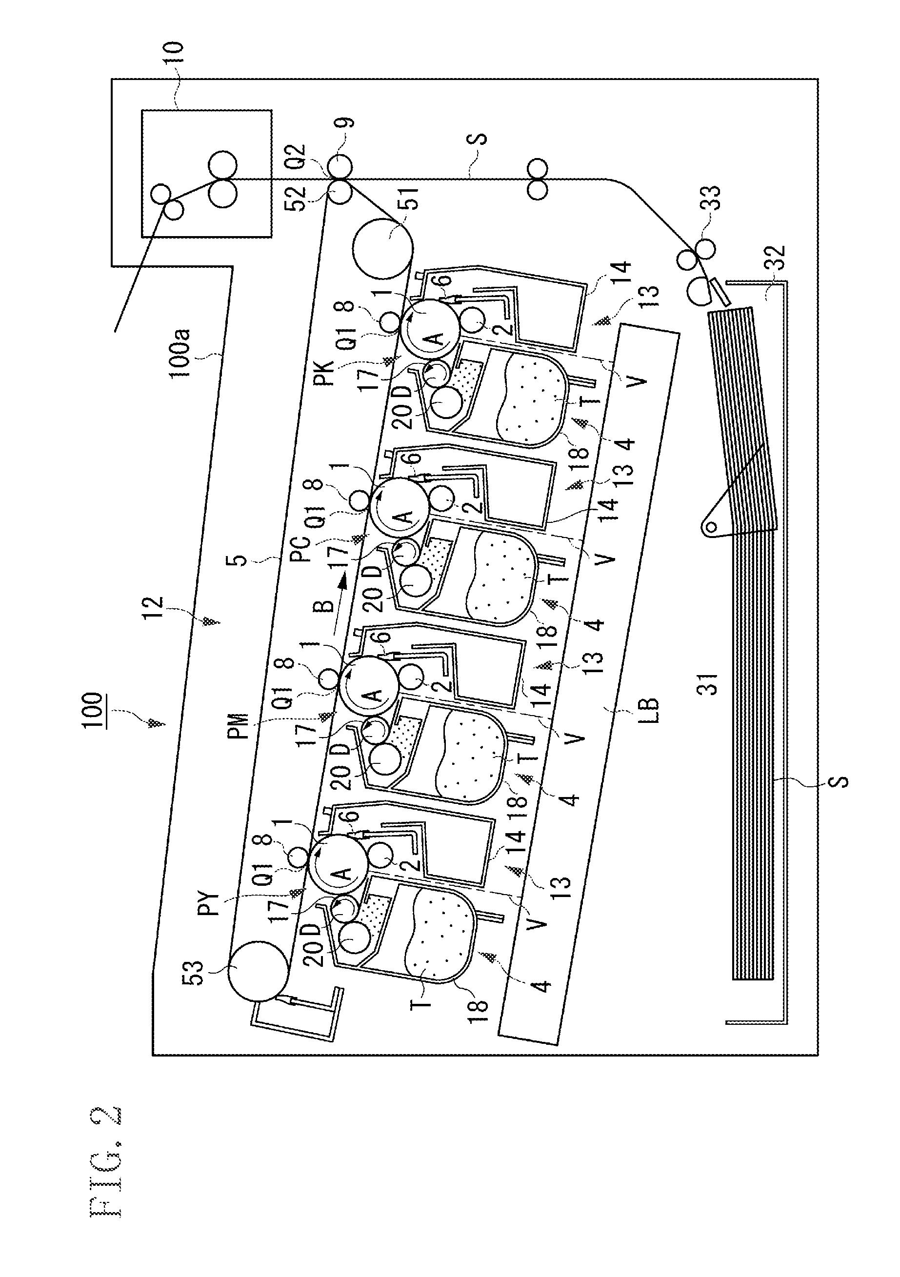
[0024]The present disclosure relates to a process cartridge used in an electrophotographic image forming apparatus, such as a copying machine and a printer, that employs an electrophotographic method. This electrophotographic image forming apparatus (hereinafter, “image forming apparatus”) forms an image on a recording material (recording medium) using an electrophotographic method. Examples of the electrophotographic image forming apparatus include a ...


PUM


Abstract

A cartridge detachably mountable to an apparatus body of an image forming apparatus, includes a grip member that is provided on the frame member for gripping the cartridge when the cartridge is mounted on or dismounted from the apparatus body, the grip member including a first molded member that is integrally molded with the frame member, and a second molded member that is integrally molded on the first molded member with a second resin after the molding of the first molded member.

Description

BACKGROUND OF THE INVENTION[0001]1. Field of the Invention[0002]The present disclosure relates to a process cartridge used in an electrophotographic image forming apparatus.[0003]2. Description of the Related Art[0004]An image forming apparatus that uses an electrophotographic process performs image recording by uniformly charging a photosensitive drum, which is an image bearing member, to form a latent image based on selective exposure on the photosensitive drum, developing the latent image with a toner, which is a developer, transferring the toner image onto a recording medium, and applying heat and pressure onto the transferred toner image to fix the toner image on the recording medium.[0005]Such an apparatus requires toner replenishment and maintenance of the various parts relating to the above-described image forming process. To facilitate the toner replenishment operation and maintenance, process cartridges have been developed. Specifically, the parts relating to the image for...

Claims


Application Information

Patent Timeline
Patent Type & Authority Applications(United States)
IPC IPC(8): G03G21/18
CPCG03G21/1839G03G21/1846
Inventor FUJIWARA, AKIHIRONITTANI, SUSUMUTANABE, MASATO
Owner CANON KK
Learn More