
Clamp Ring And Method For Manufacturing A Clamp Ring

a technology of clamp ring and clamp ring, which is applied in the direction of manufacturing tools, braking components, brake systems, etc., can solve the problems of inefficiency and waste, poor tensile strength of clamp ring, and weak end product clamp ring, so as to reduce waste scrap and eliminate waste.

Active Publication Date: 2014-03-27
HALDEX BRAKE
View PDF7 Cites 1 Cited by
  • Summary
  • Abstract
  • Description
  • Claims
  • Application Information

AI Technical Summary

Benefits of technology

[0017]Accordingly, it is an object of the present invention to provide a method and process for manufacturing a clamp ring that that eliminates and reduces waste scrap, including over 70% of the waste scrap.
[0018]It is another object of the present invention to provide a clamp ring that has an increased effective strength because it does not undergo stretching of the sidewall of the ring during manufacturing.
[0022]It is another object of the present invention to overcome prior attempts to reduce the cost of manufacturing a clamp ring. Prior attempts have been made to reduce the cost several times, however, each time a large percentage of scrap was required to make each part. There has been a long-felt need in the industry to make clamp rings having a reduced cost without having a large percentage of scrap required to make each part.
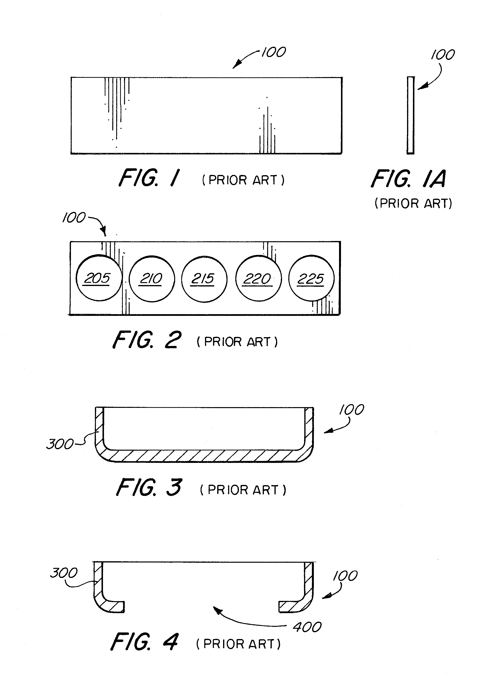
[0039]Other objectives of the invention are achieved by providing a process that teaches the manufacturing of a clamp ring that consists of slitting a steel coil to the right width and length, using coiling, rolling and / or any steel forming technique to shape the strip into a circle, and then attaching two ends together using steel joining techniques such as welding, whereby the bottom ends form the arched area and may be formed either before or after the end joining process by again using steel coiling, rolling, and forming techniques, and further requiring that the final product after assembly has to meet functional product safety requirements and where the process effectively eliminates wasted scrap.
[0040]The scrap may be effectively eliminated under the present invention, and the effective strength of the product is increased by eliminating the stretching the sidewall of the ring. The process may further involve slitting a steel coil to the right width and length, using coiling, rolling and / or any other steel forming technique to shape the strip into a circle, and then attaching two ends together using steel joining techniques. The bottom bends to form the arc'd or curved area and may be formed either before or after the end joining process by again using steel coiling, rolling, and forming techniques.

Problems solved by technology

Such a process, however, is inefficient and wasteful as over 70% of the steel sheet is thrown away as scrap.
Additionally, the end product clamp ring is generally weak as its side walls have been stretched during the manufacturing process.
This is because the drawing process also reduces the thickness in the center of the vertical side of the ring due to the stretching inherent with the drawing process, and this results in clamp rings that have decreased tensile strength.
Clamp rings that have decreased tensile strength have a shorter lifespan and are more likely to fail than clamp rings that do not undergo stretching or any other such tension or stress during the manufacturing process.
Furthermore, the prior art process is inefficient as the cost of the clamp ring part includes the cost for the entire steel sheet including the scrap, which is removed.
It is a huge waste of cost of materials to throw away the remainder of the steel sheet, while only a small portion of the sheet is used to form the clamp ring.
Clamp rings have been used on actuator products for years, and prior art attempts have been made to reduce the cost several times, however, each time a large percentage of scrap was required to make each part.
The '867 patent further does not teach a process for manufacturing a clamp ring and does not mention the benefits of establishing a manufacturing process that eliminates and reduces waste scrap.
However, the '202 patent does not teach the process of welding the ends together.
Furthermore, this patent does not teach a process for manufacturing a clamp ring and does not mention the benefits of establishing a manufacturing process that eliminates and reduces waste scrap.
However, the '432 patent does not mention the benefits of this process for eliminating and reducing waste scrap.
However, the '007 application does not mention the benefits of this process for eliminating and reducing waste scrap.
Furthermore, both these patents do not teach a process for manufacturing a clamp ring and do not mention the benefits of establishing a manufacturing process that eliminates and reduces waste scrap.

Method used


Image

  • Clamp Ring And Method For Manufacturing A Clamp Ring
  • Clamp Ring And Method For Manufacturing A Clamp Ring
  • Clamp Ring And Method For Manufacturing A Clamp Ring

Examples


Embodiment Construction

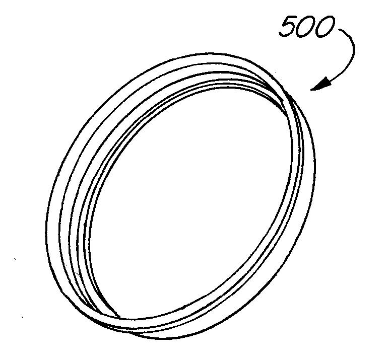
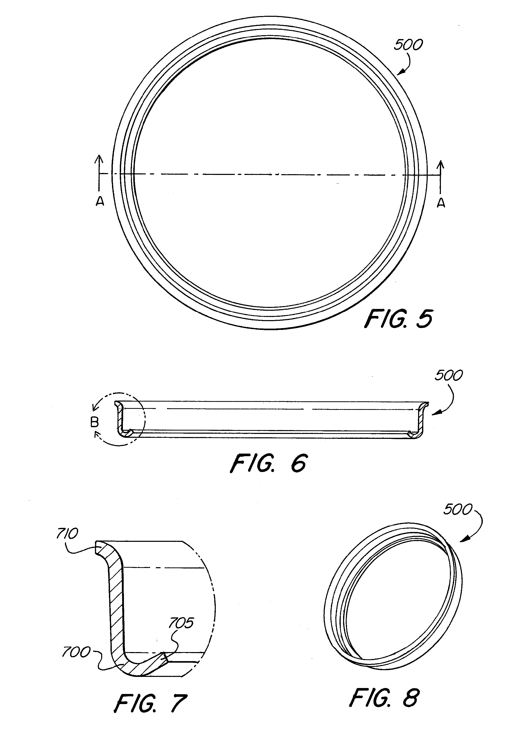
[0057]Referring to FIG. 5, clamp ring 500 of the present invention is shown. Clamp ring 500 is shown having ridges, however such ridges are not required in all embodiments of the present invention.

[0058]FIG. 6 shows a cross section view of clamp ring 500 of FIG. 5 taken along line A-A. Here the arc'd area of the clamp ring is shown taken across section B of FIG. 6. FIG. 7 shows a close up detailed view of the arc'd or curved area of FIG. 6. Arc'd section 700 is shown in FIG. 7 having a top section 710 and a bottom section 705. Arc'd section 700 is used to help the clamp ring form a seal. Arc'd section 700, top section 710 and bottom section 705 may have various angles to conform the clamp ring 500 to the member it attaches to.

[0059]FIG. 8 shows a perspective view of clamp ring 500 of the present invention.

[0060]FIG. 9 shows a side view of steel sheet 900 of the present invention and FIG. 9A shows an end view of steel sheet 900 of FIG. 9. Steel sheet 900 is shaped by a shaping techni...


PUM

PropertyMeasurementUnit
diameteraaaaaaaaaa
diameteraaaaaaaaaa
diameteraaaaaaaaaa

Abstract

A clamp ring and process for manufacturing a clamp ring to effectively reduce, if not eliminate, waste scrap from the manufacturing process. The clamp ring and process for manufacturing the same, results in clamp ring having a seam formed by a metal joining technique such as welding, brazing, bolting, soldering, and clinching.

Description

FIELD OF THE INVENTION[0001]The invention relates to a process for manufacturing a clamp ring to effectively reduce, if not eliminate, waste scrap from the manufacturing process. The process results in the formation of a clamp ring having a seam formed by a metal joining technique.BACKGROUND OF THE INVENTION[0002]Clamp rings are used in brake actuator products and are typically made from sheet steel or other types of metal. Clamp rings may be used to contact and to hold the brake actuator housing parts together to keep pressure within the actuator housing. Clamp rings may also be used to reduce the lateral movement of the piston member and may be used to seal the actuator housing during operation of a brake actuator.[0003]For clamp rings made of sheet steel, in the prior art, the steel is typically cut into strips of a width necessary to provide enough material to blank a round piece ranging from roughly six (6) inches in diameter to roughly ten (10) inches in diameter.[0004]In prio...

Claims


Application Information

Patent Timeline
Patent Type & Authority Applications(United States)
IPC IPC(8): B21D53/36F16B4/00
CPCF16B4/00B21D53/36B21D53/16B21K1/16B60T17/088F16D65/00F16B2200/509Y10T24/1457Y10T29/49826Y10T29/4998Y10T403/4933B23K31/02
Inventor SPENCER, JOHN
Owner HALDEX BRAKE
Learn More