Automatic Patting Mechanism

a technology of automatic patting and hammer, which is applied in the field of hammer, can solve the problems of insufficient relaxation of muscles for many people, pain in the neck and shoulders, and affect the whole body, and achieve the effect of relieving muscle tension

Inactive Publication Date: 2014-03-27
JOONG CHENN IND CO LTD
View PDF1 Cites 5 Cited by
  • Summary
  • Abstract
  • Description
  • Claims
  • Application Information

AI Technical Summary

Benefits of technology

[0006]It is one objective of the present invention to provide an automatic patting mechanism, which can pat on a specific part of a user's body continuously to relieve muscle tension or help the user spit out phlegm.

Problems solved by technology

Today many people lead a busy life which is highly active and busy without getting enough rest, and therefore pain may occur in the neck and shoulders.
Once the neck and shoulder pain is accumulated over a long time, it can affect the entire body, contributing to a variety of health issues.
In order to alleviate this problem, self-massage is the most common way to relieve pain in the body, but it is insufficient for many persons to relax the muscles by using their fingers, such that a manual patting massager can be used to help release tension in certain muscles.
However, the manual patting massager is operated to hit in a restricted zone and meanwhile a user is difficult to control hitting strength, resulting in that the manual patting massager will fail to meet the user's expectation.
However, the prior art device is inconvenient for the user to use because the user needs somebody's help to operate the prior art device, and further, the cam and the rod are in direct contact with each other such that the cam or the rod is easy to wear when used for long periods of time, causing a negative influence on the operation of the prior art device.

Method used


Image

  • Automatic Patting Mechanism
  • Automatic Patting Mechanism
  • Automatic Patting Mechanism

Examples


Embodiment Construction

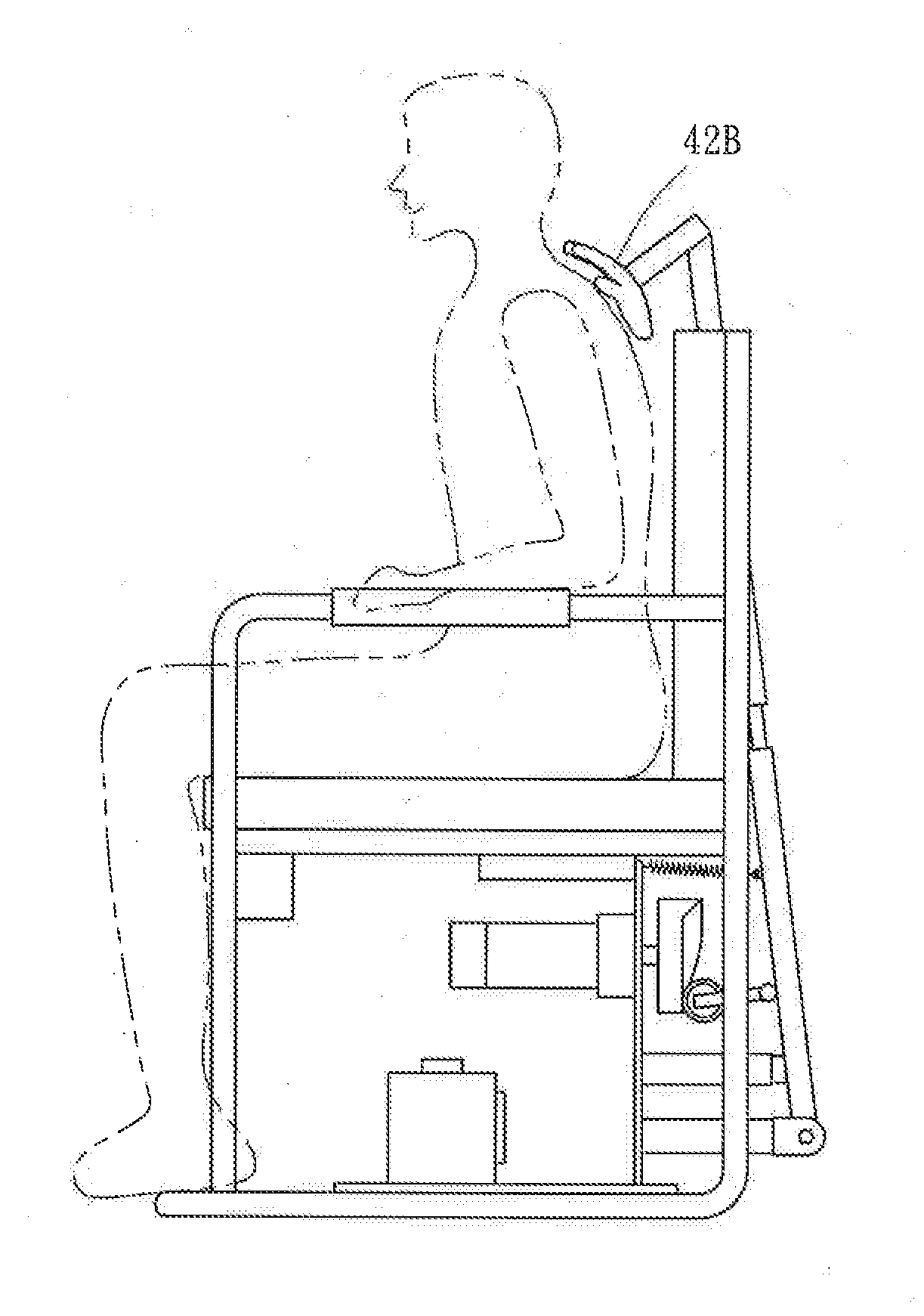
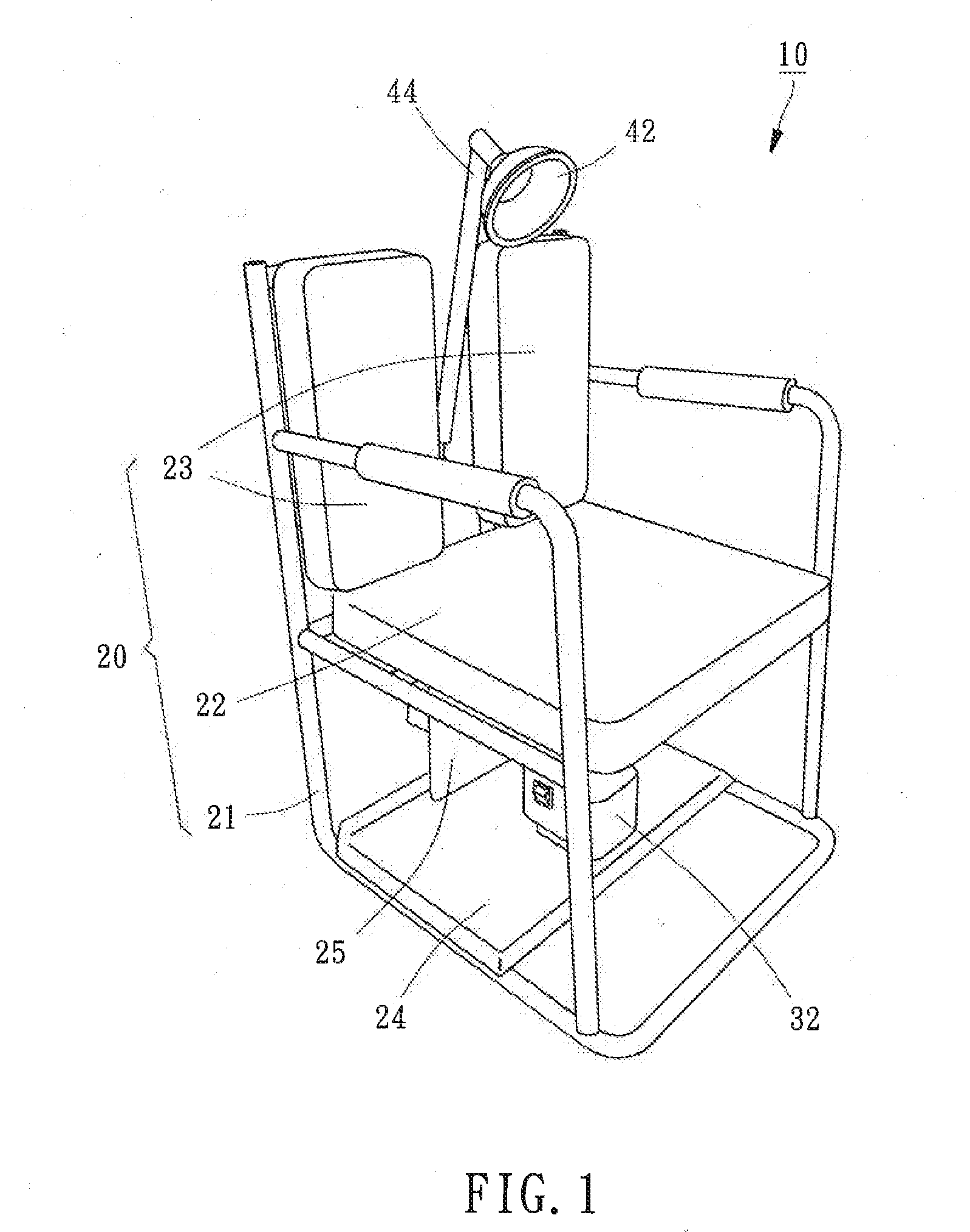
[0028]As shown in FIGS. 1 to 3, an automatic patting mechanism 10 in accordance with a first embodiment of the present invention comprises a support base 20, a driving device 30, and a patting device 40.

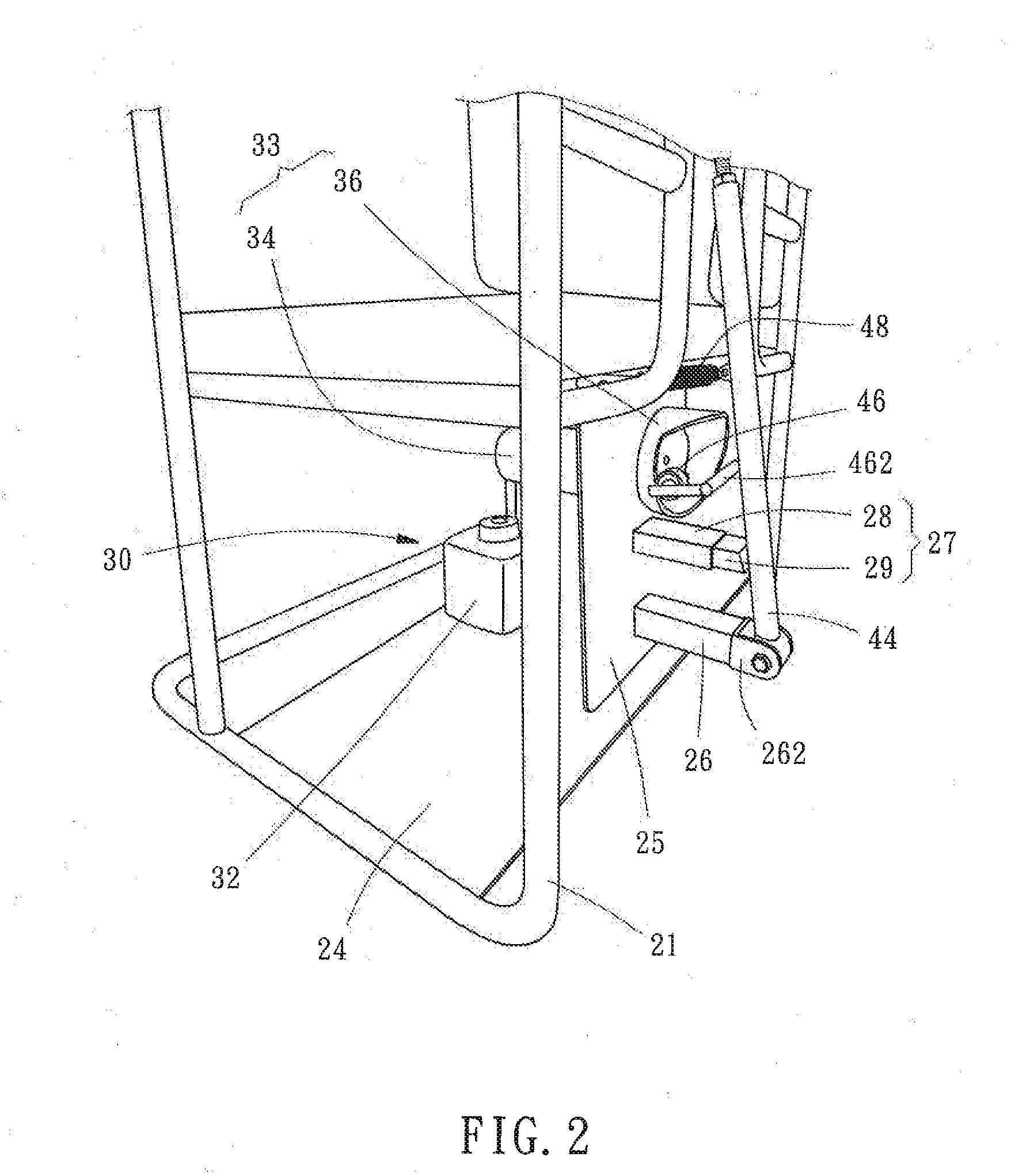
[0029]The support base 20 includes a seat frame 21 placed on the ground, a seat cushion 22 disposed on the seat frame 21 for providing a user to sit, and two spaced back cushions 23 disposed on the seat frame 21 and vertical to the seat cushion 22 for providing back support and comfort. As shown in FIG. 2, the seat frame 21 includes a bottom plate 24, a back plate 25 vertically connected with a rear side of the bottom plate 24, a first extending post 26 having one end fixedly connected with the back plate 25 and extending away from the back plate 25 to form a lug 262 at the other end, and a buffer protector 27 located above the first extending post 26 and provided with a second extending post 28 having one end fixed to the back plate 25 and extending away from the back plate 25 to be...


PUM


Abstract

A patting mechanism includes a support base for support a user, a driving device mounted to the support base and having a pushing unit, and a patting device having a rod pivotally connected with the support base, a patting member fixedly connected with the rod, and an elastic member connected between the support base and the rod. Thus, the rod is pushed to a preloaded position when the pushing unit is activated, and the rod is pulled by the elastic member to a patting position when the pushing unit is stopped working, such that the patting member is driven by the rod to pat on the user's back muscle repeatedly to relieve muscle soreness or help the user spit out phlegm.

Description

BACKGROUND OF THE INVENTION[0001]1. Field of the Invention[0002]The present invention relates generally to a patting mechanism, and more specifically to a patting mechanism, which can be operated automatically.[0003]2. Description of the Related Art[0004]Today many people lead a busy life which is highly active and busy without getting enough rest, and therefore pain may occur in the neck and shoulders. Once the neck and shoulder pain is accumulated over a long time, it can affect the entire body, contributing to a variety of health issues. In order to alleviate this problem, self-massage is the most common way to relieve pain in the body, but it is insufficient for many persons to relax the muscles by using their fingers, such that a manual patting massager can be used to help release tension in certain muscles. However, the manual patting massager is operated to hit in a restricted zone and meanwhile a user is difficult to control hitting strength, resulting in that the manual pat...

Claims


Application Information

Patent Timeline
Patent Type & Authority Applications(United States)
IPC IPC(8): A61H23/00A61H23/02
CPCA61H23/02A61H23/006A61H2201/0149A61H2201/1215A61H2201/1418A61H2201/1623A61H2205/081
Inventor CHEN, JAMES
Owner JOONG CHENN IND CO LTD
Why Eureka
Try Eureka