Electric motor-driven booster

a technology of electric motors and boosters, applied in the field of boosters, can solve the problems of reducing sealing performance, increasing sliding resistance, sealing wear, etc., and achieve the effect of reducing lateral force acting

Inactive Publication Date: 2014-04-03
HITACHI AUTOMOTIVE SYST LTD
View PDF4 Cites 32 Cited by
  • Summary
  • Abstract
  • Description
  • Claims
  • Application Information

AI Technical Summary

Benefits of technology

[0005]An object of the present invention is to provide an electric motor-driven booster configured to reduce a lateral force acting on the piston in the master cylinder.

Problems solved by technology

The lateral force acting on the master cylinder piston causes an increase in sliding resistance, degradation of sealing performance, and seal wear.

Method used


Image

  • Electric motor-driven booster
  • Electric motor-driven booster
  • Electric motor-driven booster

Examples


Embodiment Construction

[0010]One embodiment of the present invention will be explained below in detail with reference to the accompanying drawings.

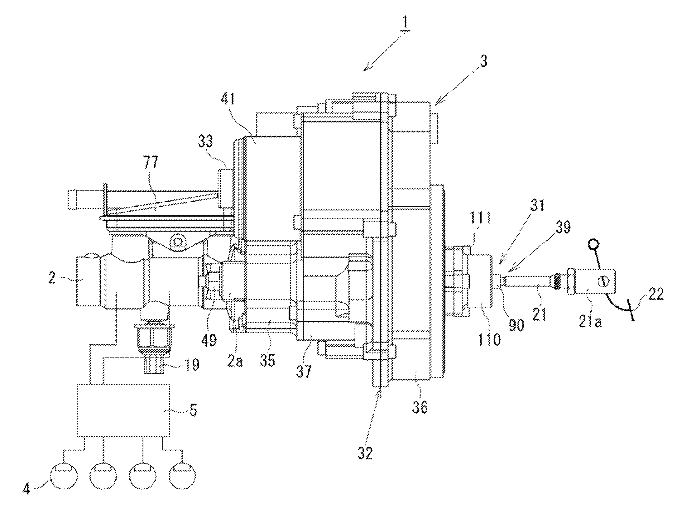
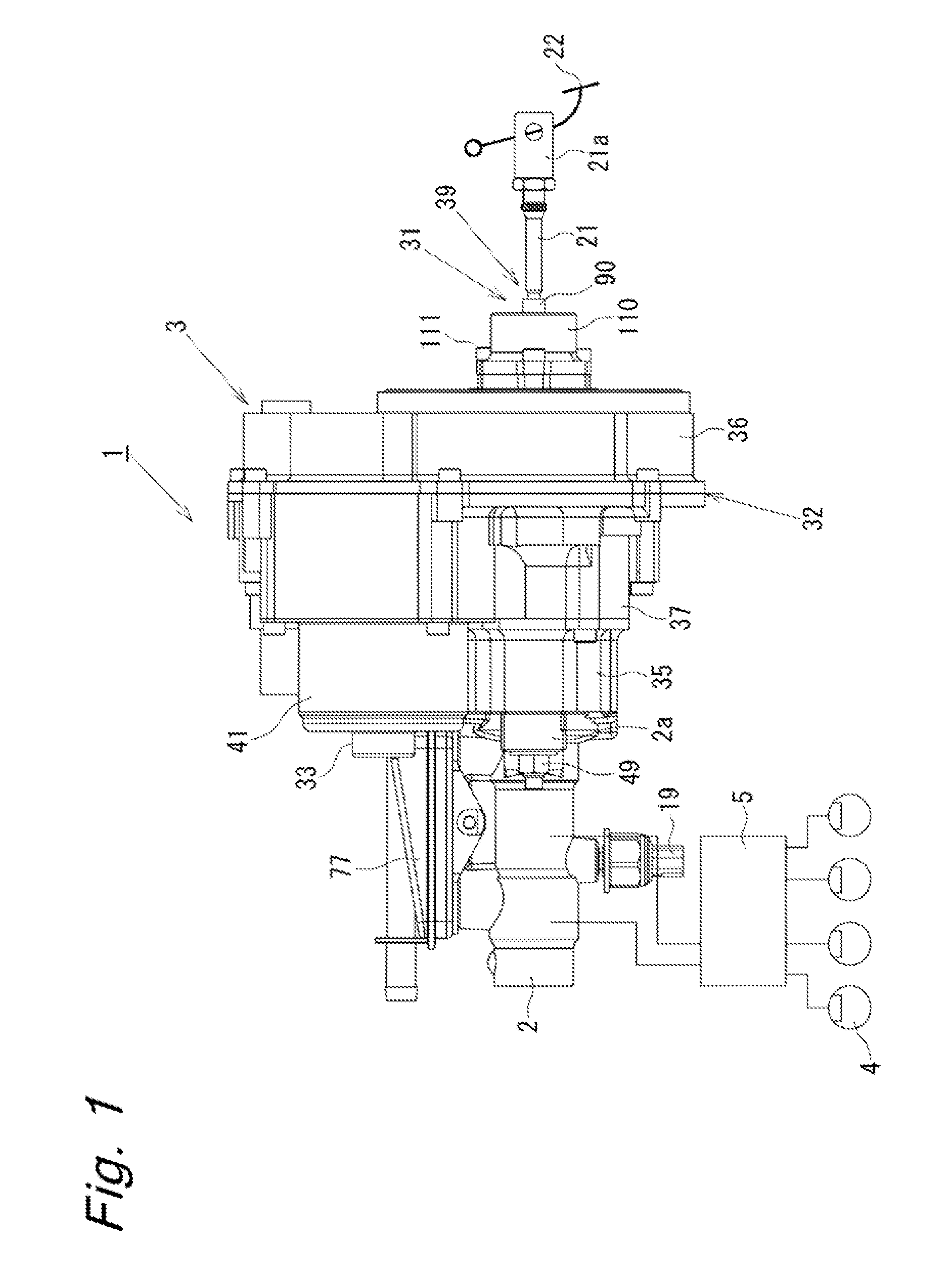
[0011]FIG. 1 shows a brake system of an automobile incorporating an electric motor-driven booster according to this embodiment. As shown in FIG. 1, the brake system 1 has a master cylinder 2 for generating brake hydraulic pressure, and an electric motor-driven booster 3 connected to the master cylinder 2 as one unit to propel a primary piston 72 (piston) in the master cylinder 2. The brake system 1 further has hydraulic wheel cylinders 4 connected to the master cylinder 2 and supplied with, the brake hydraulic pressure to generate a braking force for each wheel. Further, the brake system 1 has a hydraulic pressure control unit 5 interposed between the master cylinder 2 and the wheel cylinders 4, and an in-vehicle controller (not shown) for controlling the operations of the electric motor-driven booster 3 and the hydraulic pressure control unit 5.
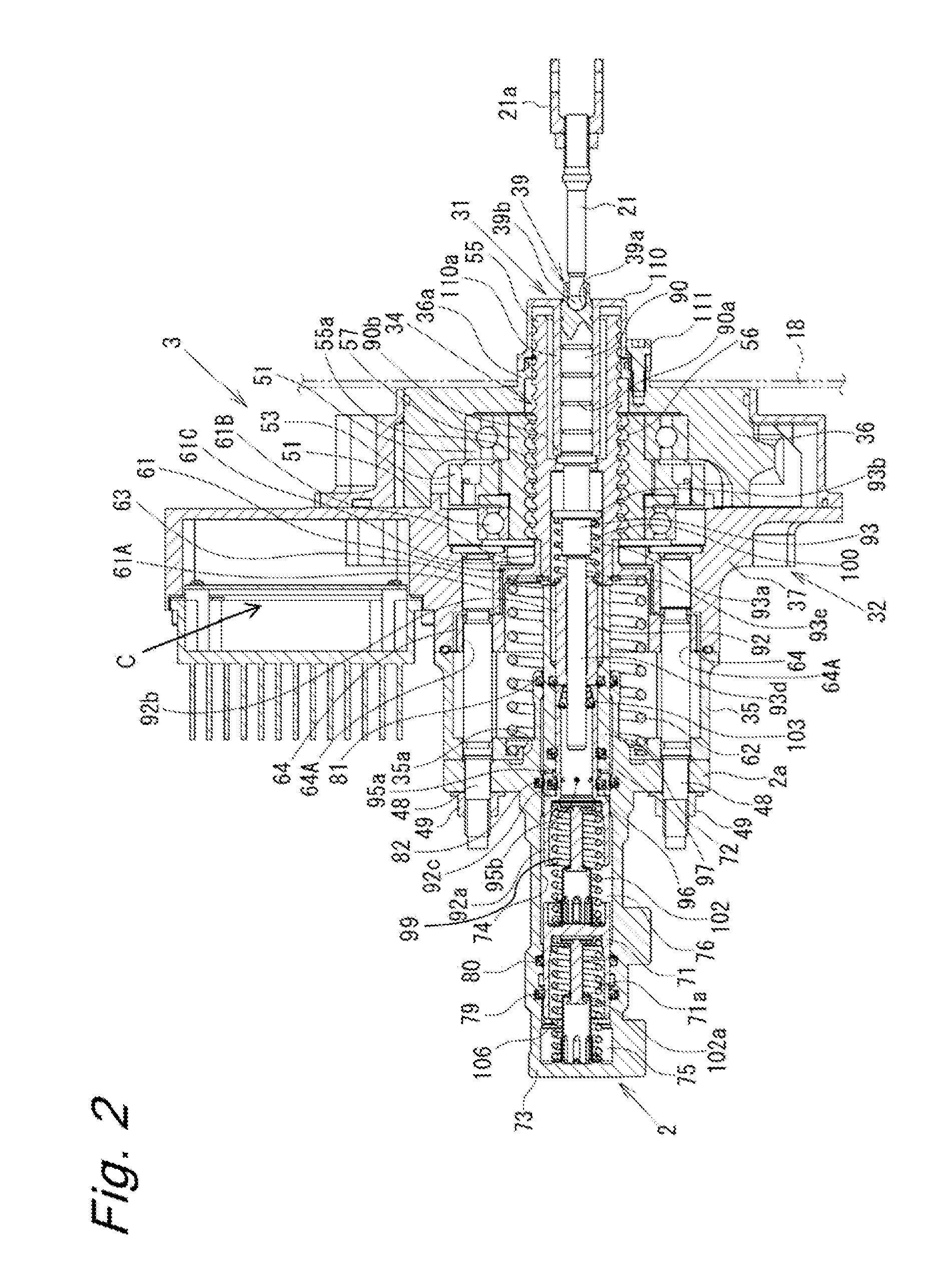
[0012]As shown ...


PUM


Abstract

An electric motor is controlled according to an operation of a brake pedal connected to an input rod to drive a ball-screw mechanism through a transmission mechanism, thereby propelling a primary piston and a subpiston to generate brake hydraulic pressure in a master cylinder. The brake hydraulic pressure in the master cylinder is received with an input piston and transmitted to the brake pedal through a plunger rod and the input rod. The input rod and the plunger rod are tiltably connected, through a ball joint, and the plunger rod is axially slidably guided by a guide part of a rear cover. Thus, a lateral force acting on the primary piston or the subpiston is reduced to prevent an increase in sliding resistance and degradation of sealing performance.

Description

BACKGROUND OF INVENTION[0001]The present invention relates to boosters incorporated in brake systems of automobiles and other vehicles, and, more particularly, to an electric motor-driven booster generating brake hydraulic pressure by driving a piston in a master cylinder with an electric motor according to an amount of operation of a brake pedal.[0002]A publicly known electric motor-driven booster is disclosed, for example, in Japanese Patent Application Publication No. 2012-35814. With the electric motor-driven booster, an electric motor is controlled by a controller according to an amount of driver's operation of a brake pedal, and the rotary motion of the electric motor is converted into a rectilinear motion through a ball-screw mechanism, which is a rotation-rectilinear motion conversion mechanism, to propel a piston in a master cylinder, thereby generating brake hydraulic pressure. Further, an input piston connected to the brake pedal is inserted into the master cylinder to tr...

Claims


Application Information

Patent Timeline
Patent Type & Authority Applications(United States)
IPC IPC(8): B60T13/74
CPCB60T13/745B60T8/4077B60T11/16B60T13/573B60T13/74
Inventor YOSHIZU, RIKIYAUSUI, TAKUYAODAIRA, ATSUSHI
Owner HITACHI AUTOMOTIVE SYST LTD
Why Eureka
Try Eureka