Device for separating a fluid mass flow

a fluid mass flow and fluid technology, applied in the direction of nuclear engineering, nuclear elements, greenhouse gas reduction, etc., to achieve the effect of low maintenan

Inactive Publication Date: 2014-04-03
AREVA GMBH
View PDF10 Cites 14 Cited by
  • Summary
  • Abstract
  • Description
  • Claims
  • Application Information

AI Technical Summary

Benefits of technology

[0008]One object of the invention is, therefore, to specify a device by which a fluid mass flow, in particular in a nuclear plant, can be separated into substreams with a stipulated mass flow ratio, the mass flow ratio of the substreams being as constant as possible under variable pressure, temperature and velocity distributions in the fluid mass flow. Furthermore, the aim is to ensure that the substreams are as stable and free of turbulence a

Problems solved by technology

A particular challenge is presented by the object of configuring the flow separation such that substreams which flu

Method used


Image

  • Device for separating a fluid mass flow
  • Device for separating a fluid mass flow
  • Device for separating a fluid mass flow

Examples


Embodiment Construction

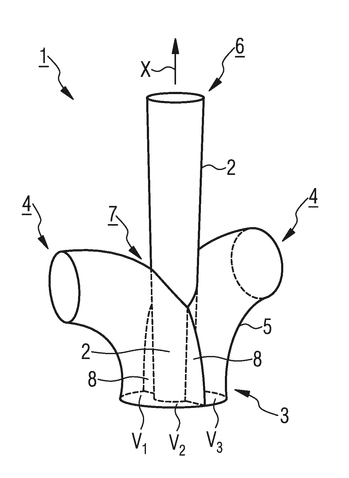
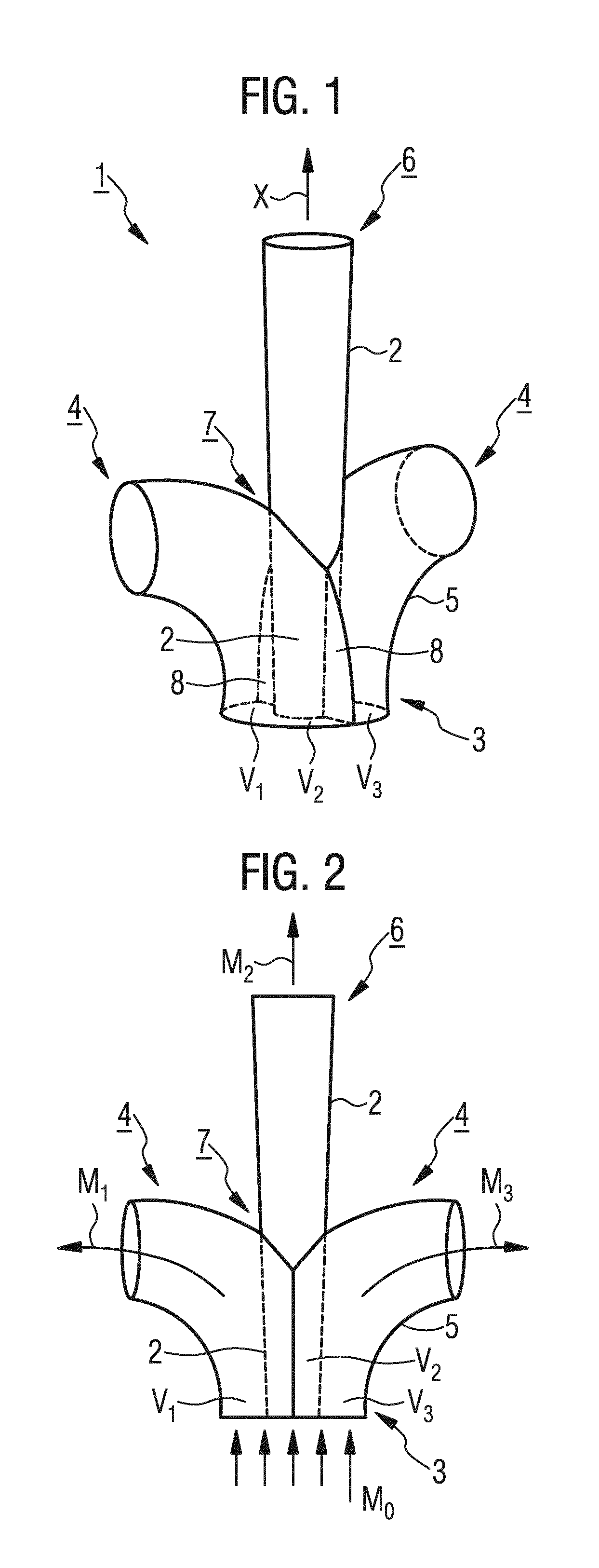
[0047]Identical parts in FIG. 1 to FIG. 4 are given the same reference symbols. These reference symbols are also used in FIG. 5, in which, however, additional reference symbols are also used in view of an alternative linguistic characterization of the invention. Referring now to the figures of the drawings in detail and first, particularly to FIG. 1 thereof, there is shown a device 1, also designated as a distributor, for separating a fluid mass flow Mo. The device 1 contains a conically tapered inner guide pipe 2, which is concentrically surrounded at the narrower end by a tubular primary end piece 3. The primary end piece 3 is connected to two identically shaped secondary end pieces 4 arranged opposite one another with respect to the inner guide pipe 2, so that the primary end piece 3 together with the two secondary end pieces 4 form a pipe branch 5. In the wider end region of the inner guide pipe 2, which region is arranged opposite the primary end piece 3 with respect to an axis...


PUM


Abstract

A device separates a fluid mass flow in a nuclear plant. The device contains a primary end piece for conducting the fluid mass flow and a plurality of secondary end pieces for conducting a plurality of separate partial flows of the fluid mass flow. A number of separating elements is provided in the area within the primary end piece, and each of the partial areas defined by the separating element or the separating elements opens in a secondary end piece clearly assigned to the partial area.

Description

CROSS-REFERENCE TO RELATED APPLICATION[0001]This is a continuation application, under 35 U.S.C. §120, of copending international application No. PCT / EP2012 / 072510, filed Nov. 13, 2012, which designated the United States; this application also claims the priority, under 35 U.S.C. §119, of German patent application No. DE 10 2012 201 129.3, filed Jan. 26, 2012; the prior applications are herewith incorporated by reference in their entireties.BACKGROUND OF THE INVENTIONField of the Invention[0002]The invention relates to a device for separating a fluid mass flow, in particular for use in a nuclear plant.[0003]Devices of this type are usually configured as subsegments of multiple-way distributers formed as pipelines and are used in order to separate from one another liquid, gas or vapor streams (fluid mass flows) routed in pipelines and to split them into a plurality of substreams. They may also be employed correspondingly, in a reversal of the flow conditions, in order to bring togethe...

Claims


Application Information

Patent Timeline
IPC IPC(8): F16L41/02
CPCF16L41/02F16L41/03G21C15/00G21D1/00Y02E30/00Y02E30/30Y10T137/85938
Inventor BUETTNER, ROBERTSCHULZE, GUENTHERWALTERSKOETTER, RALF
Owner AREVA GMBH
Why Eureka
Try Eureka