Touch and motion detection using surface map, object shadow and a single camera

a technology of surface map and object shadow, applied in the field of touch and motion detection using surface map, object shadow and a single camera, can solve the problems of more space and higher cost of two cameras in the produ

Active Publication Date: 2014-04-10
HONG KONG APPLIED SCI & TECH RES INST
View PDF21 Cites 25 Cited by
  • Summary
  • Abstract
  • Description
  • Claims
  • Application Information

AI Technical Summary

Benefits of technology

[0008]The present invention provides an optical method for obtaining positional or motional information of an object with respect to a reference surface, including detecting if the object touches the reference surface. The reference surface may be substantially flat or non-flat. The object has a pre-determined reference peripheral point. A projector and a camera are used in the disclosed optical method. The projector and the camera are arranged such that when the object not touching the reference surface is illuminated by the projector, a part of the object's shadow formed on the reference surface along a topographical surface line is observable by the camera, the aforesaid part of the shadow having a length being usable for uniquely determining the object's height above the reference surface. The topographical surface line is formed by projecting a line-of-sight path joining the camera and the reference peripheral point on the reference surface. In particular, a surface map is used for mapping a location on the reference surface and a corresponding location in a camera-captured image having a view o

Problems solved by technology

Using two cameras instead of one camera has practical disadvantages in making a produ

Method used


Image

  • Touch and motion detection using surface map, object shadow and a single camera
  • Touch and motion detection using surface map, object shadow and a single camera
  • Touch and motion detection using surface map, object shadow and a single camera

Examples


Embodiment Construction

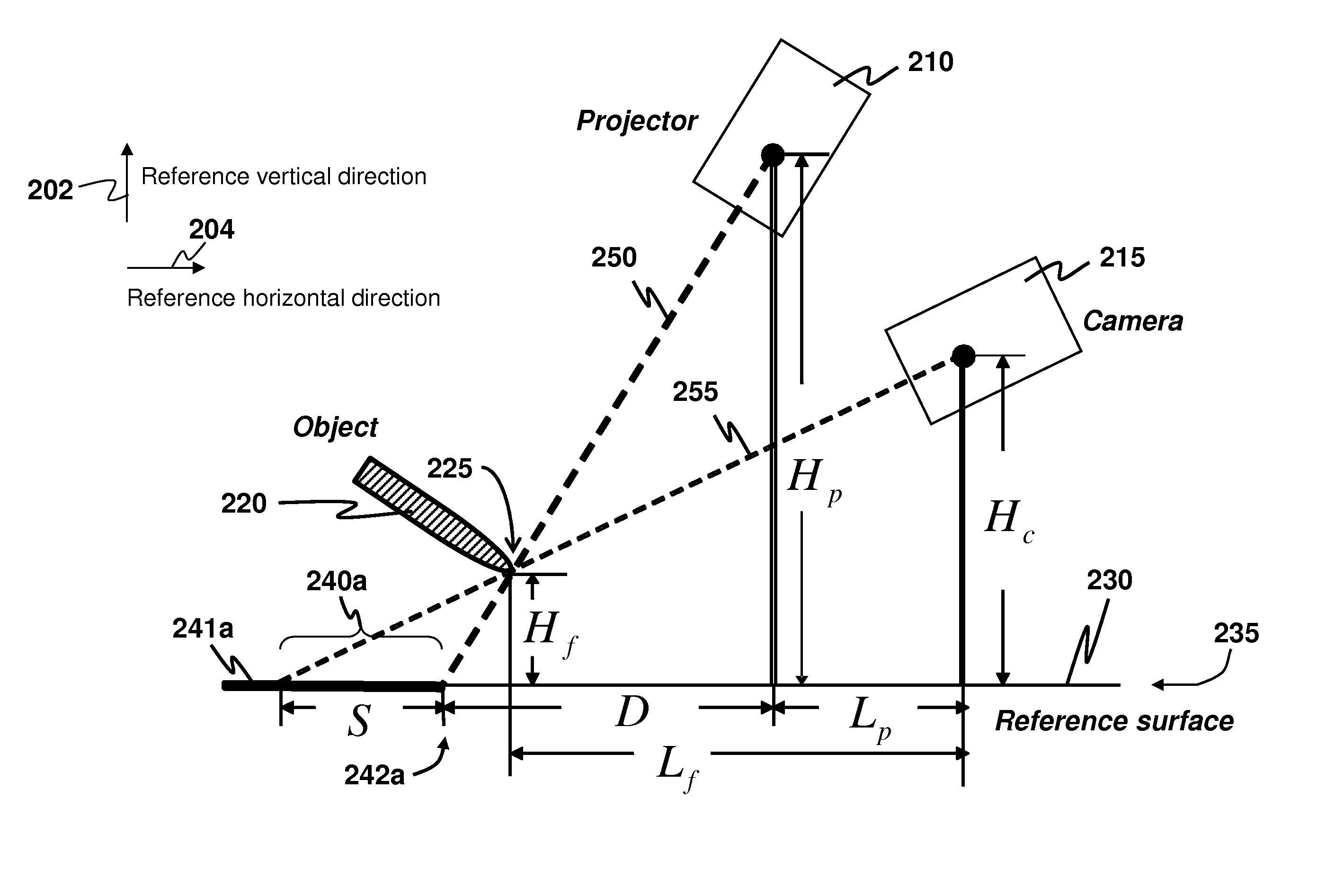
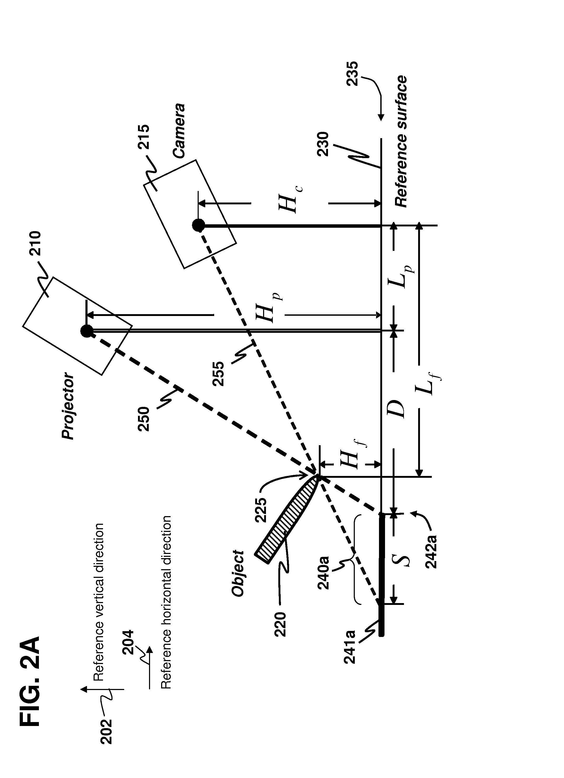
[0028]As used herein, “a reference vertical direction” and “a reference horizontal direction” are defined as two directions that are mutually orthogonal, but these two directions are not further defined with reference to the direction of planetary gravity. Provided that a reference surface is substantially flat, the reference vertical direction is defined herein as a direction substantially perpendicular to the reference surface and the reference horizontal direction is defined with reference to the reference vertical direction. The reference surface may be, for example, a floor surface or a surface of a wall. In case the reference surface is not substantially flat, an imaginary flat surface sufficiently representative to the reference surface over surface roughness thereon is used instead of the original reference surface in defining the reference vertical direction. That is, the reference vertical direction is defined herein as a direction substantially perpendicular to this imagi...


PUM


Abstract

The present invention provides an optical method and a system for obtaining positional and/or motional information of an object with respect to a reference surface, including detecting if the object touches the reference surface, by using a projector and one camera. A surface map is used for mapping a location on the reference surface and a corresponding location in a camera-captured image having a view of the reference surface. In particular, a camera-observed shadow length, i.e. a length of the object's shadow observable by the camera, estimated by using the surface map, is used to compute the object's height above the reference surface (a Z coordinate). Whether or not the object touches the reference surface is also obtainable. After an XY coordinate is estimated, a 3D coordinate of the object is obtained. By computing a time sequence of 3D coordinates, the motional information, such as velocity and acceleration, is obtainable.

Description

CROSS-REFERENCE TO RELATED APPLICATION[0001]This application is a continuation-in-part of U.S. patent application Ser. No. 13 / 474,567 filed May 17, 2012, the disclosure of which is herein incorporated by reference in its entirety.COPYRIGHT NOTICE[0002]A portion of the disclosure of this patent document contains material, which is subject to copyright protection. The copyright owner has no objection to the facsimile reproduction by anyone of the patent document or the patent disclosure, as it appears in the Patent and Trademark Office patent file or records, but otherwise reserves all copyright rights whatsoever.FIELD OF THE INVENTION[0003]The present invention generally relates to optically determining positional or motional information of an object with respect to a reference surface, including information on whether the object touches the reference surface. In particular, the present invention relates to a method and a system for optically determining such positional or motional i...

Claims


Application Information

Patent Timeline
IPC IPC(8): G01B11/02G06T7/60
CPCG06T7/60G01B11/022G06F3/042G06F3/0425G06F3/0426
Inventor ZHANG, WEI
Owner HONG KONG APPLIED SCI & TECH RES INST
Why Eureka
Try Eureka