Card connector

a card connector and card body technology, applied in the direction of coupling device connection, coupling/disconnecting parts engagement/disengagement, electrical apparatus, etc., can solve the problems of failure to meet the universal design requirements of electronic products, failure to further miniaturize the overall size of the electronic card connector, and relatively bulky conventional card connectors. achieve the effect of simple structural design and stable card insertion and removal mechanism

Inactive Publication Date: 2014-04-10
TRANSCENDENT ELECTRONICS
View PDF0 Cites 14 Cited by
  • Summary
  • Abstract
  • Description
  • Claims
  • Application Information

AI Technical Summary

Benefits of technology

[0008]From the forgoing structure disclosed by the present invention, the size (width) reduction of the card ejection mechanism and the overall size of the card connector is attributable to a linear and reciprocating motion (movement) of the card ejection mechanism. Moreover, the ejection rod of the card ejection mechanism can be linearly moved to squeeze the spring leaf of the base for the spring leaf to disengage from the engagement part of the tongue, thereby achieving a stable card insertion and removal mechanism with the simple structural design of the card connector of the present invention.

Problems solved by technology

However, due to the heart-shaped slot of the slider, the conventional card connector becomes relatively bulky.
The relatively bulky slider forces the insulation body to reserve a larger space for mounting the slider so that the overall size of the electronic card connector fails to be further miniaturized.
Such failure certainly run counter to the universal design requirement of electronic products, that is, being compact, thin and lightweight.
As a result, when the downward stress on the elastic pressing plate is excessively high, the guiding rod can be no longer operated smoothly and the electronic card connector is unable to be normally operated.

Method used


Image

  • Card connector
  • Card connector
  • Card connector

Examples


first embodiment

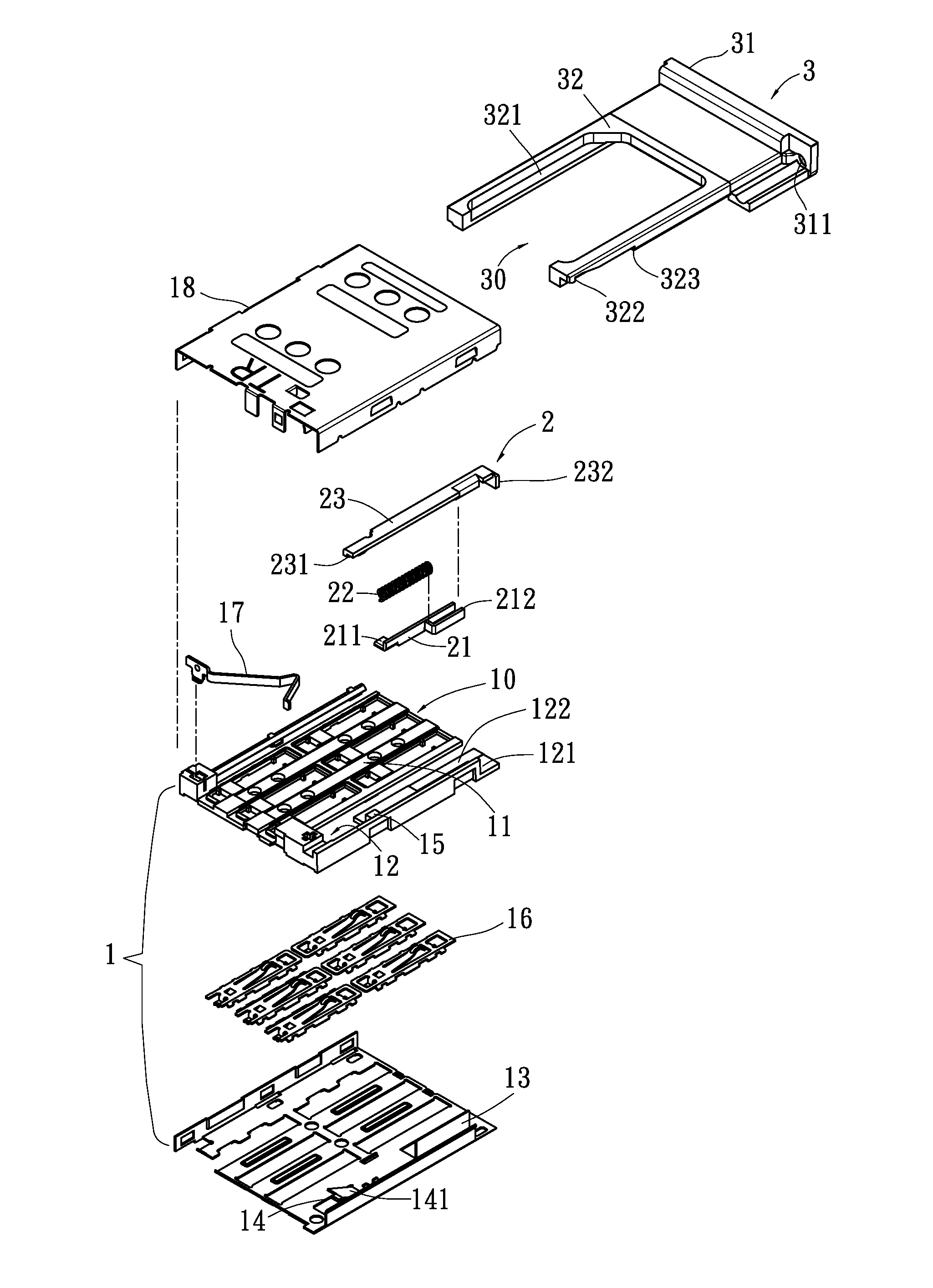
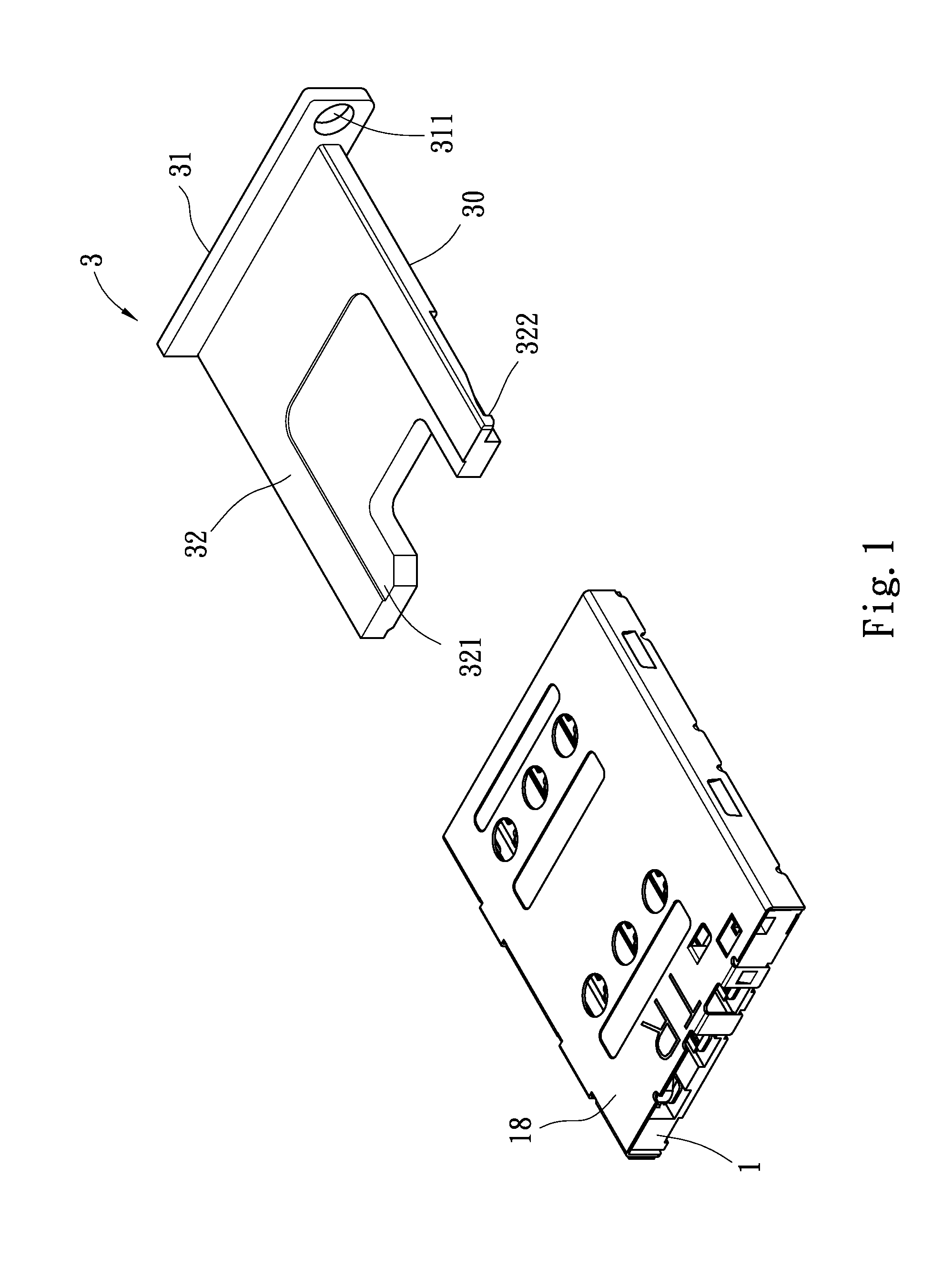
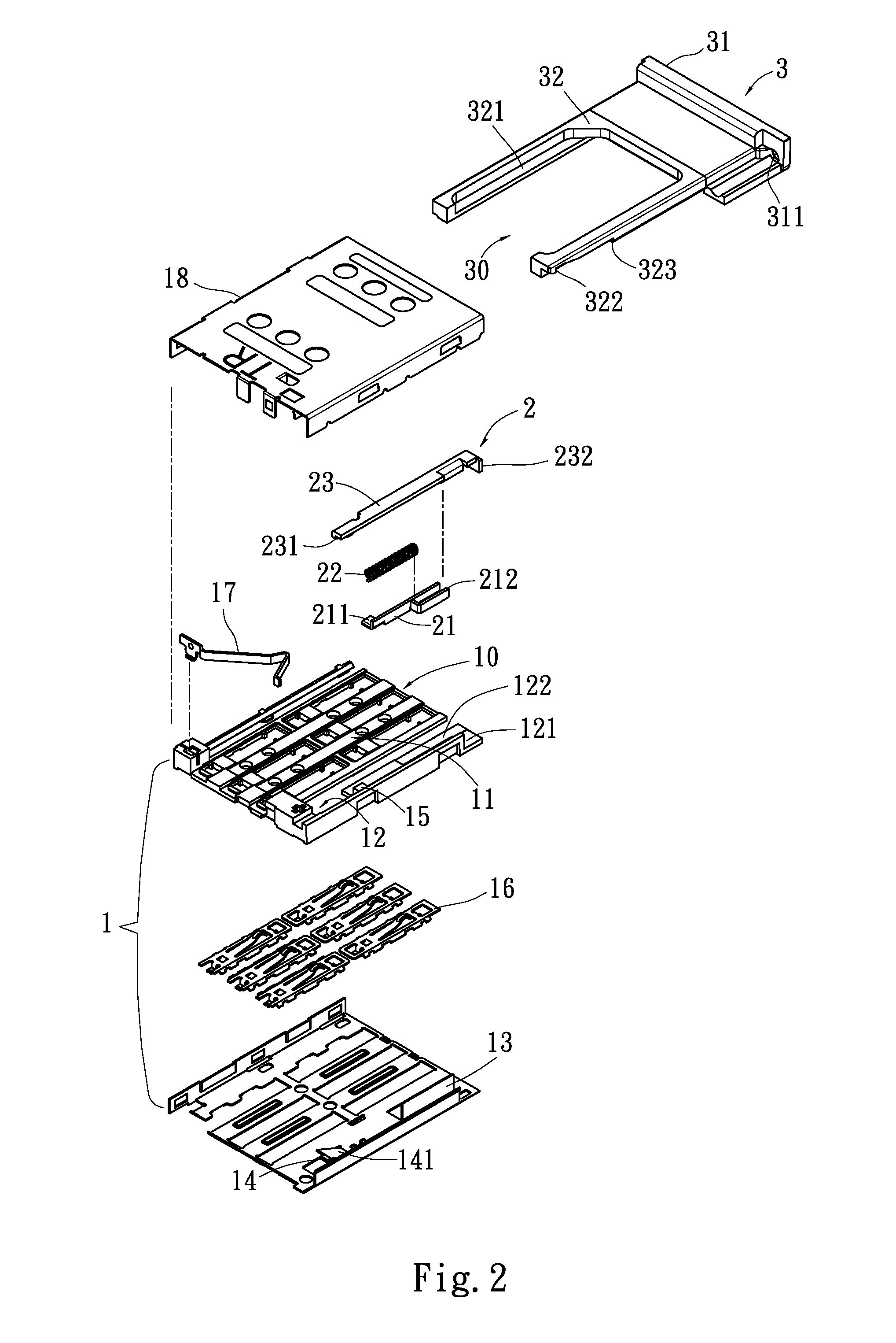
[0021]With reference to FIGS. 1 and 2, a card connector in accordance with the present invention has a base 1, a card ejection mechanism 2 and a card seat 3.

[0022]The base 1 has an opening 10, a first space 11, a second space 12, a partition plate 13, a spring leaf 14, a protrusion 15, at least one set of terminals 16, at least one detection terminal 17 and a cover 18. The opening 10 is formed through a front of the base 1. The first space 11 and the second space 12 are defined inside the base 1, are adjacent to each other, and communicate with the first opening 10. The partition plate 13 is formed on the base 1 to divide the second space 12 into a first setting zone 121 and a sliding zone 122. The spring leaf 14 is incised from and bent upwards from the base 1, and is located on straight-line paths extending from the setting zone 121 and the sliding zone 122. The protrusion 15 is formed on and protrudes from the base 1 and is located on a straight-line path extending from the setti...

second embodiment

[0027]With reference to FIGS. 8 and 9, a card connector in accordance with the present invention is shown. The spring leaf 14 is incised from a side of the base 1 and is bent inwards, has a contact surface 141 facing the first space 11, and is located on straight-line paths extending from the setting zone 121 and the sliding zone 122. When the card seat 3 is inserted in the base 1, the engagement part 322 of the card seat 3 engages the spring leaf 14 of the base 1 as shown in FIG. 8, and the card seat 3 can be securely held in the base 1. When the card seat is removed from the base 1, similarly, the pressing part 232 of the ejection rod 23 is pressed, and the ejection rod 23 is then linearly movable so that the extrusion part 231 of the ejection rod 23 can abut against the spring leaf 14 of the base 1, the spring leaf 14 of the base 1 disengages from engagement part 322 of the card seat 3 as shown in FIG. 9, and the card seat can be removed from the base 1.

third embodiment

[0028]With reference to FIGS. 10 and 11, a card connector in accordance with the present invention is shown. The spring leaf 14 is incised from the cover and is bent toward an inner portion of the base 1, has a contact surface 141 facing the inner portion of the base 1, and is located on straight-line paths extending from the setting zone 121 and the sliding zone 122 of base 1. When the card seat is inserted in the base 1, the engagement part 322 of the card seat 3 engages the spring leaf 14 of the base 1 as shown in FIG. 10 and the card seat 3 can be securely held inside the base 1. When the card seat 3 is removed from the base 1, the pressing part 232 of the ejection rod 23 is pressed, and the ejection rod 23 is then linearly movable so that the extrusion part 231 of the ejection rod 23 can abut against the spring leaf 14 of the base 1, the spring leaf 14 of the base 1 disengages from engagement part 322 of the card seat 3 as shown in FIG. 11, and the card seat can be removed from...


PUM


Abstract

A card connector has a base, a card ejection mechanism and a card seat. The base has a first space for at least one set of terminals to be mounted therein, a second space with the card ejection mechanism mounted therein, and a spring leaf mounted in the second space. The card seat has a tongue. The tongue has a card-holding slot formed in a top of the tongue and mounted inside the first space of the base, and an engagement part formed on a bottom of the tongue and corresponding to the spring leaf of the base. When the card seat is inserted in the base, the engagement part of the tongue engages the spring leaf of the base for the card seat to be securely held by the base. When the card seat is removed from the base, the card ejection mechanism is pressed to squeeze the spring leaf of the base for the engagement part of the tongue to disengage from the spring leaf and the card seat can be ejected from the base.

Description

BACKGROUND OF THE INVENTION[0001]1. Field of the Invention[0002]The present invention relates to a card connector and more particularly to a card connector capable of easily and effectively reducing overall size thereof.[0003]2. Description of the Related Art[0004]To keep abreast with the rapid development of electronic and information technologies, consumer electronic products, such as mobile phones, MP3 players, digital cameras and so on, have their market growth in greater amount every year and apparently become indispensable products and leading trend of the new era. When operated, these electronic products need to record and store text data, static image data or dynamic audio / video data through a storage card (memory card). Hence, currently, almost every electronic product is equipped with an electronic card connector to connect with external storage cards. As to the conventional card connectors in the market, irrespective of single card connectors or combo card connectors, the...

Claims


Application Information

Patent Timeline
Patent Type & Authority Applications(United States)
IPC IPC(8): H01R13/635
CPCH01R13/635H01R12/7094H01R12/714
Inventor HSU, KUEI-SANG
Owner TRANSCENDENT ELECTRONICS
Why Eureka
Try Eureka