System for Mounting an Abrasive Tool to a Drive Plate of Grinding and Polishing Machines

a technology of grinding and polishing machines and mounting systems, which is applied in the direction of metal-working equipment, metal-working equipment, manufacturing tools, etc., can solve the problems of quick change of defective segments or even addition, and achieve the effect of efficient change of tools

Inactive Publication Date: 2014-04-17
BERG IND +1
View PDF0 Cites 2 Cited by
  • Summary
  • Abstract
  • Description
  • Claims
  • Application Information

AI Technical Summary

Benefits of technology

[0006]Disclosed is a system for efficiently changing the tools on the drive plate of a grinder or polishing machine. A system in accordance with the teachings of the present invention uses an intermediate element to which the tools are mounted. This arrangement is then mounted to the drive plate.
[0008]There are many advantages in using a quick change system in accordance with the teachings of this present invention. The uniqueness of the present invention allows for adaptation to a variety of different types of machines. The system in accordance with the teachings of this invention is at least as fast and in most cases faster than other systems for changing tools. It also provides a more stable, less complicated and more reliable functioning of the tools than most other systems. A system in accordance with the teachings of the present invention works very quickly without having complicated designs and parts. As importantly, it facilitates the use of one standard tool size for several sizes and weights of equipment making it a great deal more efficient. The cost of manufacturing is reduced because there is no need for replacing the whole head plate, but just the segments. There is also a possibility to quickly change a defective segment or even add more segments on the same plate for more aggressive work. It also provides the ability to custom balance the machine due to the irregularities of the surface being worked on.

Problems solved by technology

There is also a possibility to quickly change a defective segment or even add more segments on the same plate for more aggressive work.

Method used


Image

  • System for Mounting an Abrasive Tool to a Drive Plate of Grinding and Polishing Machines
  • System for Mounting an Abrasive Tool to a Drive Plate of Grinding and Polishing Machines
  • System for Mounting an Abrasive Tool to a Drive Plate of Grinding and Polishing Machines

Examples


Embodiment Construction

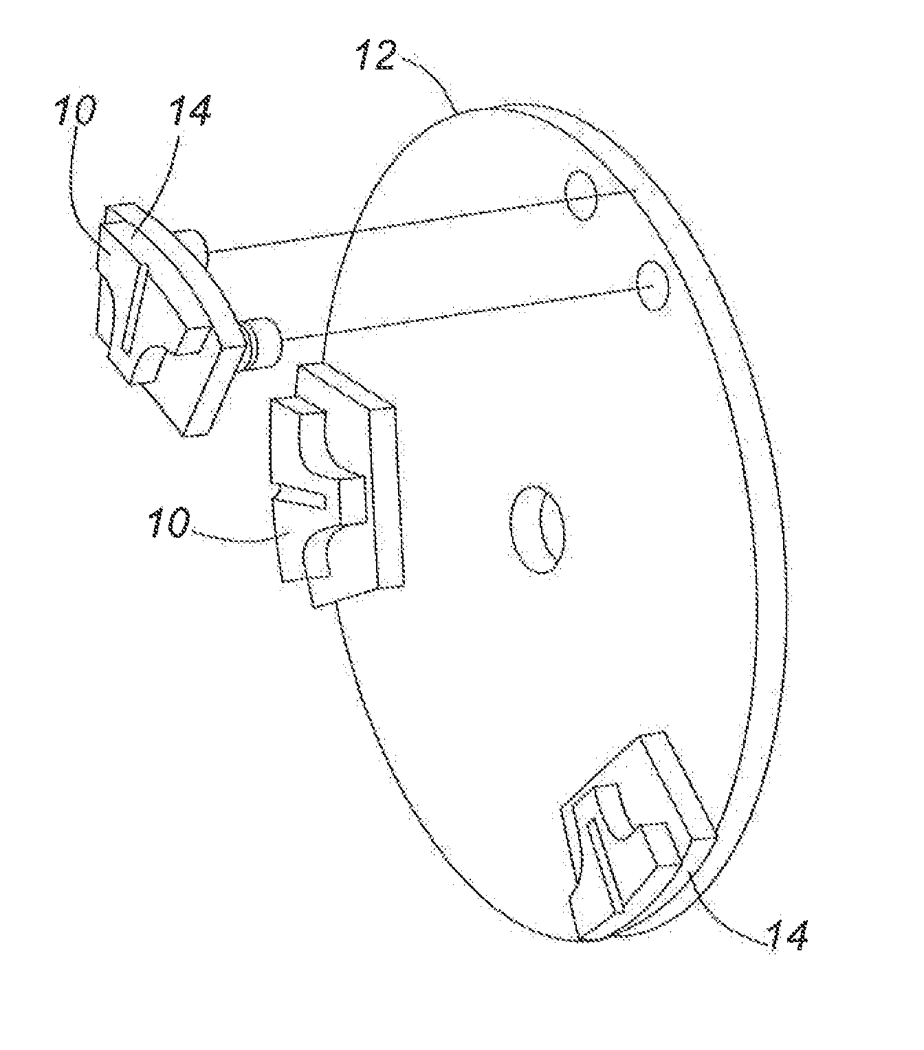
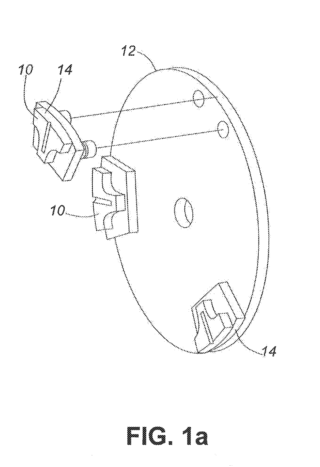
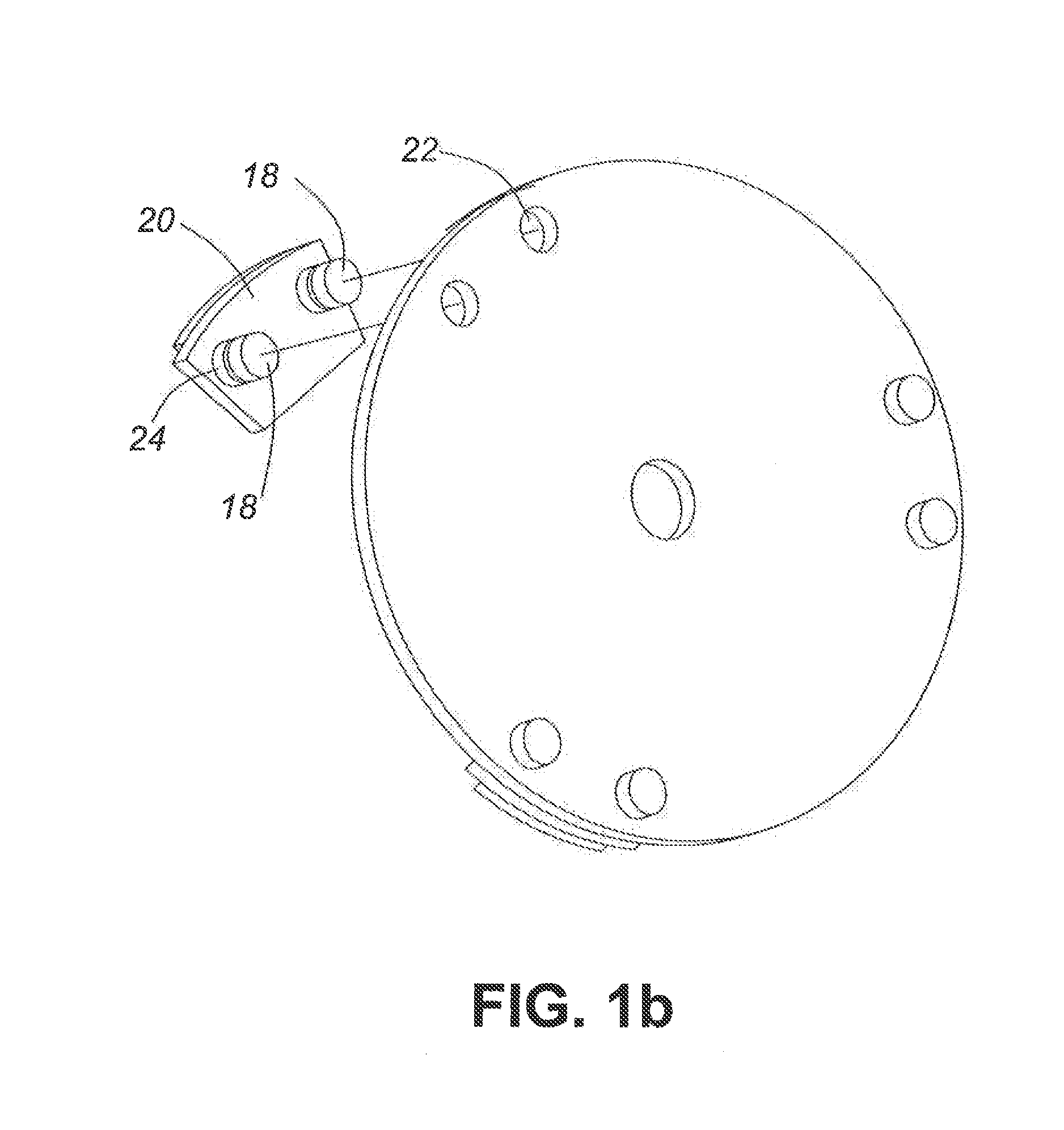
[0027]Disclosed in accordance with the teachings of this present invention is a quick change system to change the polishing or grinding tool for a polisher or grinding machine. The tool can be any suitable tool or abrasive material, such an abrasive diamond in various matrices, sandpaper, Velcro-backed polishing pads, etc. A drive plate is located on the bottom of the polisher or grinding machine. Embodiments of this invention provide an efficient way to attach at least one tool to the drive plate. Embodiments of this invention use an intermediate element between the drive plate and the abrasive tool. A securing means is used to fasten the abrasive tool to the intermediate element and a second securing means is used to fasten the intermediate element to the drive plate.

[0028]In general, embodiments of the invention have been designed to work on Werkmaster™ machines. Werkmaster™ machines use multiple grinding heads that required specific tool plate sizes that are unique to the Werkma...


PUM

PropertyMeasurementUnit
abrasiveaaaaaaaaaa
timeaaaaaaaaaa
sizesaaaaaaaaaa

Abstract

Thus, according to one aspect, the invention provides a system for mounting an abrasive tool to a drive plate of a polisher or grinding tool, the system comprising: an intermediate element mounted to a surface of the drive plate via a first securing means; and a second securing means for securing the abrasive tool to the intermediate element. The intermediate element may be a tool mounting plate and the second securing means is at least one pin and spring assembly. The intermediate element may be a ring and the second securing element comprises magnets and pins. The intermediate element may be a circular bracket and the second securing element comprises rotary slot attachment.

Description

CROSS-REFERENCE TO RELATED APPLICATION [0001]This application is a divisional application of U.S. patent application Ser. No. 12 / 687,953, now pending, which claims the benefit of U.S. Provisional Application No. 61 / 144,923 filed Jan. 15, 2009, both incorporated by reference herein.FIELD OF THE INVENTION [0002]The present invention relates to grinding and polishing machines. More specifically, the present invention relates to a system to change between multiple abrasive tools on grinding and polishing machines.BACKGROUND OF THE INVENTION [0003]It is known in the art that grinding and polishing machines uses multiple grinding and polishing tools or abrasive tools. And quite often it is necessary to change between tools. There are very slow methods that involve bolting each of several grinding plates to one or many drive plates on grinding and polishing machines. Changing tools can take as much as 20 minutes. There are also various proprietary quick-change systems that are only availab...

Claims


Application Information

Patent Timeline
Patent Type & Authority Applications(United States)
IPC IPC(8): B24D7/16
CPCB24D7/16B24D7/066Y10T29/53704
Inventor STARK, HARVEYROGERS, OWENWILSON, BRIANCHABROS, ALEX
Owner BERG IND
Why Eureka
Try Eureka