Dry sprinkler assemblies

a technology of dry sprinklers and assemblies, which is applied in fire rescue and other directions, can solve the problems of not showing a single dry sprinkler structure, inhibiting the ability of dry sprinklers to achieve particular rated k-factors,

Active Publication Date: 2014-04-17
TYCO FIRE PRODS LP
View PDF6 Cites 16 Cited by
  • Summary
  • Abstract
  • Description
  • Claims
  • Application Information

AI Technical Summary

Benefits of technology

[0017]In an alternate embodiment of the dry sprinkler, an inlet fitting includes a proximal head portion and a distal body portion, the inlet fitting having a coupling arrangement for at least one of a thread-type coupling and groove-type coupling arrangement for connection to a fluid supply pipe. The preferred sprinkler includes an internal structural assembly having a seal assembly supported by a fluid tube that is in contact with a sealing surface in an unactuated state of the sprinkler, and is spaced from the sealing surface in an actuated state of the sprinkler. The seal assembly is preferably engaged with a proximal end of the fluid tube such that the seal assembly translates with respect to the fluid tube upon translation of the internal structural assembly in a transition of the sprinkler from an unactuated to an actuated state. Preferably, the fluid tube translates a first distance with respect to the sealing surface and the seal assembly translating a second distance with respect to the sealing surface a second distance greater than the first distance. In one embodiment, the sprinkler includes an inlet fitting providing for each of thread-type coupling and groove-type coupling arrangement for connection to a fluid supply pipe.

Problems solved by technology

The presence of the seal assembly in the internal volume of the inlet after actuation may present an unsuitable resistance to water flow thereby inhibiting the ability of the dry sprinkler to achieve particular rated K-factors with certain nominal sized threaded inlets.
More specifically, Jackson et al. does not show a single dry sprinkler structure having two or more coupling configurations to provide multiple modes for connection to a system piping.

Method used


Image

  • Dry sprinkler assemblies
  • Dry sprinkler assemblies
  • Dry sprinkler assemblies

Examples


Embodiment Construction

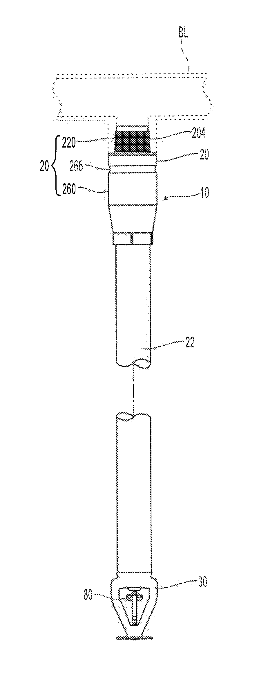
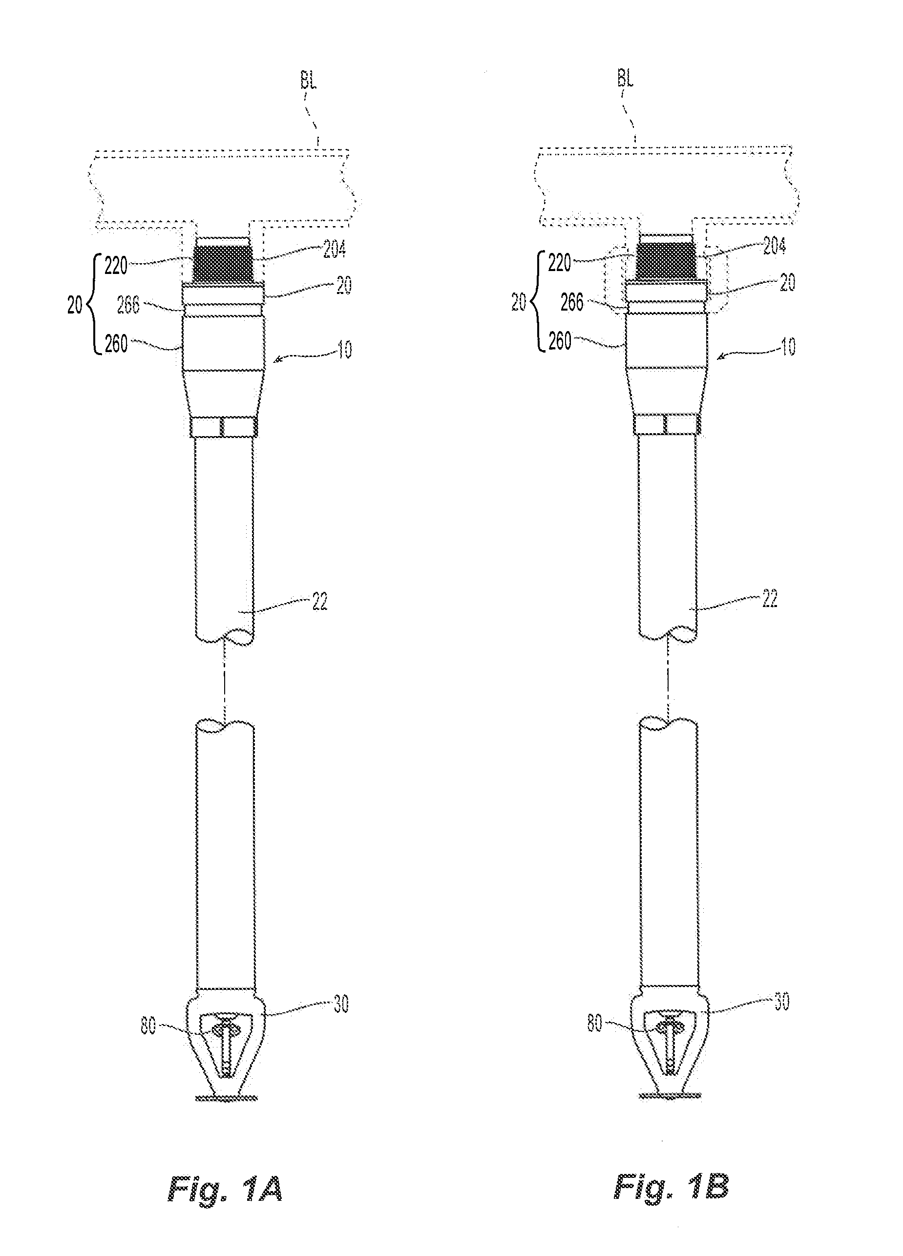
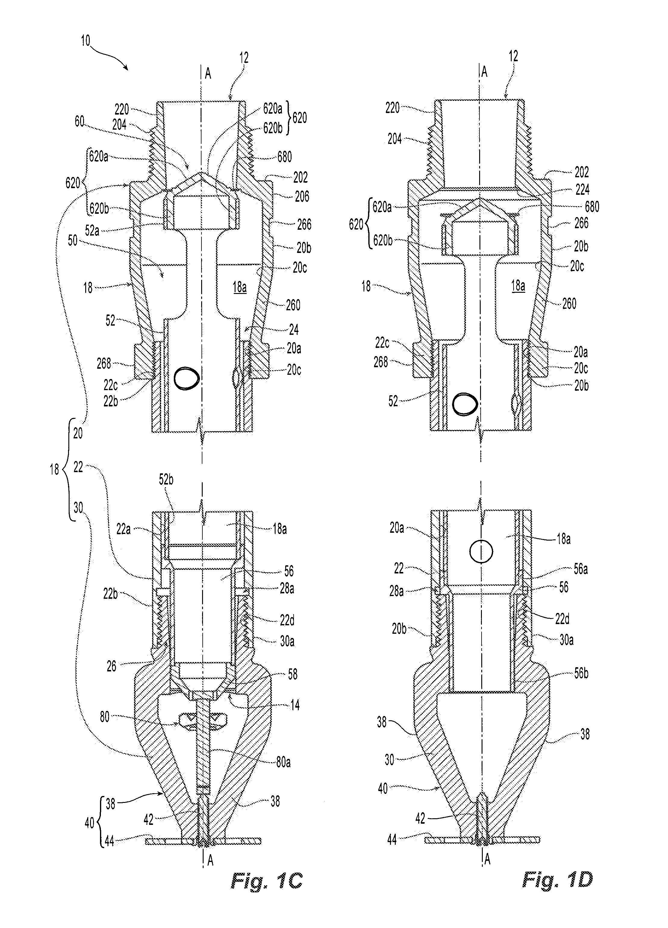
[0039]FIGS. 1A and 1B illustrate a preferred embodiment of a dry sprinkler 10 installed and coupled to a pipe fitting of a piping network, which is supplied with a fire fighting fluid, e.g., fluid from a pressurized fluid supply source. The preferred embodiments described herein include dry sprinklers that are suitable for use, for example, with a dry pipe system (e.g. at least a portion of the system is exposed to freezing temperatures in an unheated portion of a building) or a wet pipe system (e.g. the entire system is not exposed to freezing temperatures in an unheated portion of a building) or both. Fluid supply piping systems may be installed in accordance with the NFPA 13. As seen in FIGS. 1C and 1D, the dry sprinkler 10 includes an outer structure assembly 18, an inner structural assembly 50, and a thermal trigger 80. The outer structure assembly 18 defines an internal passageway 18a that extends along a central longitudinal axis A-A between a proximal inlet end 12 and a dist...


PUM

PropertyMeasurementUnit
lengthaaaaaaaaaa
lengthaaaaaaaaaa
lengthaaaaaaaaaa

Abstract

A dry sprinkler for a fire protection system having a configuration with one or more coupling arrangements for connection to a fluid supply piping of the system. The dry sprinkler structure further includes an inner surface and inner assembly to provide a preferred discharge performance. The dry sprinkler provides for a flow rate from the outlet of the sprinkler in accordance with the start pressure at the inlet of the sprinkler and the rated discharge coefficient, K factor, ranging between 16.8 GPM / PSI½ and 33.6 GPM / PSI½

Description

PRIORITY CLAIM & INCORPORATION BY REFERENCE[0001]This international application claims the benefit of priority to U.S. Provisional Patent Application No. 61 / 501,959, filed Jun. 28, 2011, which is incorporated by reference in its entirety.BACKGROUND OF THE INVENTION[0002]Automatic sprinkler systems are some of the most widely used devices for fire protection. These systems have sprinklers that are activated once the ambient temperature in an environment, such as a room or building exceeds a predetermined value. Once activated, the sprinklers distribute fire-extinguishing fluid, preferably water, in the room or building. A sprinkler system is considered effective if it extinguishes or prevents growth of a fire. The effectiveness of a sprinkler is dependent upon the sprinkler consistently delivering an expected flow rate of fluid from its outlet for a given pressure at its inlet. The discharge coefficient or K-factor of a sprinkler allows for an approximation of flow rate to be expecte...

Claims


Application Information

Patent Timeline
Patent Type & Authority Applications(United States)
IPC IPC(8): A62C35/68
CPCA62C35/68A62C35/62Y10T29/49826A62C37/12A62C37/14
Inventor RINGER, YORAMSILVA, JR., MANUEL R.COLETTA, GEORGE B.LEDUC, ROGER H.WEED, SEAN D.
Owner TYCO FIRE PRODS LP
Why Eureka
Try Eureka