Head mountable display

a display and display element technology, applied in the field of head mountable displays, can solve the problems of so-called retinal rivalry and the practical limits of the extent to which the display elements of the hmd can be toed-out, and achieve the effect of reducing luning, accurately and realistically, and improving the mitigation of luning

Active Publication Date: 2014-04-17
SONY COMPUTER ENTERTAINMENT INC
View PDF3 Cites 139 Cited by
  • Summary
  • Abstract
  • Description
  • Claims
  • Application Information

AI Technical Summary

Benefits of technology

[0016]a controller operable to control light emitted by the light emitting elements dependent upon the video signals so as to reduce luning, wherein the light emitted by the at least one light emitting element on the left-hand display element is dependent upon image content of the right-hand or left-hand image, and the light emitted by the at least one light emitting element on the right-hand display element is dependent upon the image content of the left or right image respectively.
[0018]However, in toeing out the display elements, a problem known as so-called retinal rivalry may occur because only single images are provided to the user's eyes where binocular images are normally expected. A result of this is that a psychophysical effect termed “luning” can occur, which manifests itself as darkened portions in the image rendered by the brain of the user that correspond to the inner edges of the display elements. Consequently, there are practical limits to the extent to which display elements of an HMD can be toed-out. The present invention can mitigate the effect of luning by introducing light which is dependent upon the periphery of the images provided to the user's eye into the central nasal region of the an HMD. This technique can reduce luning, therefore allowing display elements of an HMD to be toed-out without necessarily adversely affecting the FOV or user experience.
[0020]In one embodiment of the invention a colour of the light emitted by the at least one light emitting element on the left-hand display element corresponds to a colour of the right-hand periphery of the image provided by the left-hand display element, and a colour of the light emitted by the at least one light emitting element on the right-hand display element corresponds to a colour of the left-hand periphery of the image provided by the right-hand display element. Controlling the light emitting elements to emit light having a colour which corresponds to the colours of the periphery of the images provided by the relevant display elements improves the mitigation of luning. When corresponding colours are emitted the images provided by the display elements will be more accurately and realistically extended into the central nasal area of the user's vision therefore reducing luning and allowing for an increased FOV via toeing-out of the display elements.

Problems solved by technology

Other HMDs, however, allow the user only to see the displayed images, which is to say that they obscure the real world environment surrounding the user.
However, in toeing out the display elements, a problem known as so-called retinal rivalry may occur because only single images are provided to the user's eyes where binocular images are normally expected.
Consequently, there are practical limits to the extent to which display elements of an HMD can be toed-out.

Method used


Image

  • Head mountable display
  • Head mountable display
  • Head mountable display

Examples


Embodiment Construction

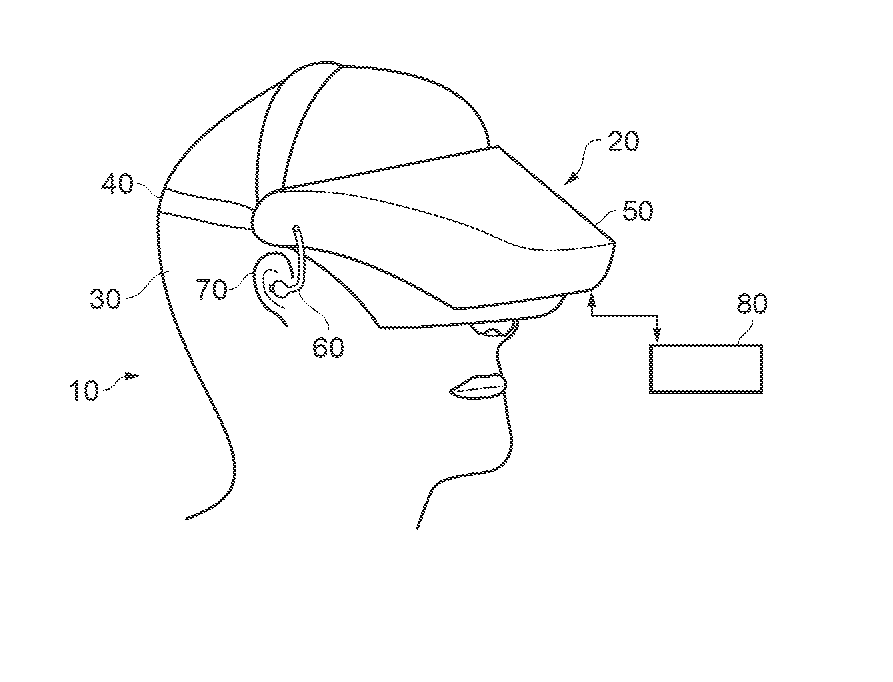
[0039]Referring now to FIG. 1, a user 10 is wearing an HMD 20 on the users head 30. The HMD comprises a frame 40, in this example formed of a rear strap and a top strap, and a display portion 50.

[0040]The HMD of FIG. 1 completely obscures the users view of the surrounding environment. All that the user can see is the pair of images displayed within the HMD.

[0041]The HMD has associated headphone earpieces 60 which fit into the users left and right ears 70. The earpieces 60 replay an audio signal provided from an external source, which may be the same as the video signal source which provides the video signal for display to the user's eyes.

[0042]In operation, a video signal is provided for display by the HMD. This could be provided by an external video signal source 80 such as a video games machine or data processing apparatus (such as a personal computer), in which case the signals could be transmitted to the HMD by a wired or a wireless connection. Examples of suitable wireless conn...


PUM


Abstract

A head-mountable display comprises a frame configured to be mounted on a user's head. The frame defines left and right-hand eye display positions that are positioned in front of the respective eyes of the user. A left-hand display element is mounted with respect to the left-hand eye display position, and is operable to provide an image from a left-hand video signal to the user's left eye. A right-hand display element mounted with respect to the right-hand eye display position, and is operable to provide an image from a right-hand video signal to the user's right eye. At least one light emitting element is positioned on a right-hand periphery of the left-hand display element and at least one light emitting element is positioned on a left-hand periphery of the right-hand display element. A controller controls light emitted by the light emitting elements dependent upon the video signals to reduce luning.

Description

BACKGROUND[0001]1. Field of the Invention[0002]This invention relates to head-mountable displays.[0003]2. Description of the Related Art[0004]The “background” description provided herein is for the purpose of generally presenting the context of the disclosure. Work of the presently named inventors, to the extent it is described in this background section, as well as aspects of the description which may not otherwise qualify as prior art at the time of filing, are neither expressly or impliedly admitted as prior art against the present invention.[0005]A head-mountable display (HMD) is an image or video display device which may be worn on the head or as part of a helmet. Either one eye or both eyes are provided with small electronic display devices.[0006]Some HMDs allow a displayed image to be superimposed on a real-world view. This type of HMD can be referred to as an optical see-through HMD and generally requires the display devices to be positioned somewhere other than directly in ...

Claims


Application Information

Patent Timeline
Patent Type & Authority Applications(United States)
IPC IPC(8): G02B27/01
CPCG02B27/017G02B27/0172
Inventor BICKERSTAFF, IAN HENRYBENSON, SIMON MARK
Owner SONY COMPUTER ENTERTAINMENT INC
Why Eureka
Try Eureka