Coordinate positioning module, optical touch system, method of detecting power of an active touch medium, and method of switching modes of the active touch medium

a technology of optical touch and positioning module, which is applied in the direction of instruments, computing, electric digital data processing, etc., can solve the problems of reducing the detection sensitivity of the optical touch apparatus, dim light emitted from the stylus, and high manufacturing cost of the conventional active radiating stylus with the power detecting component, so as to prolong the usage time of the active touch medium and save power consumption

Active Publication Date: 2014-04-17
PIXART IMAGING INC
View PDF2 Cites 6 Cited by
  • Summary
  • Abstract
  • Description
  • Claims
  • Application Information

AI Technical Summary

Benefits of technology

The present invention is an optical touch system that uses a coordinate positioning module to detect the intensity of the optical signal outputted from an active touch medium. This system can determine the power of the optical signal by comparing its intensity to thresholds, and can switch between low power modes based on the surrounding circumstances, location, and personal demand. The system does not require any additional electronic components and can be used as a reference for switching operational modes or providing a prompt message of battery exchange for the active touch medium.

Problems solved by technology

When the battery is deficient in power, the light emitted from the stylus is dim, and detection sensitivity of the optical touch apparatus is decreased.
However, manufacturing cost of the conventional active radiating stylus with the power detecting component is expensive, and volume of the conventional active radiating stylus is huge in order to accommodate the power detecting component.
The conventional active radiating stylus has drawbacks of expensive cost, enormous volume and inconvenient operation.

Method used


Image

  • Coordinate positioning module, optical touch system, method of detecting power of an active touch medium, and method of switching modes of the active touch medium
  • Coordinate positioning module, optical touch system, method of detecting power of an active touch medium, and method of switching modes of the active touch medium
  • Coordinate positioning module, optical touch system, method of detecting power of an active touch medium, and method of switching modes of the active touch medium

Examples


Embodiment Construction

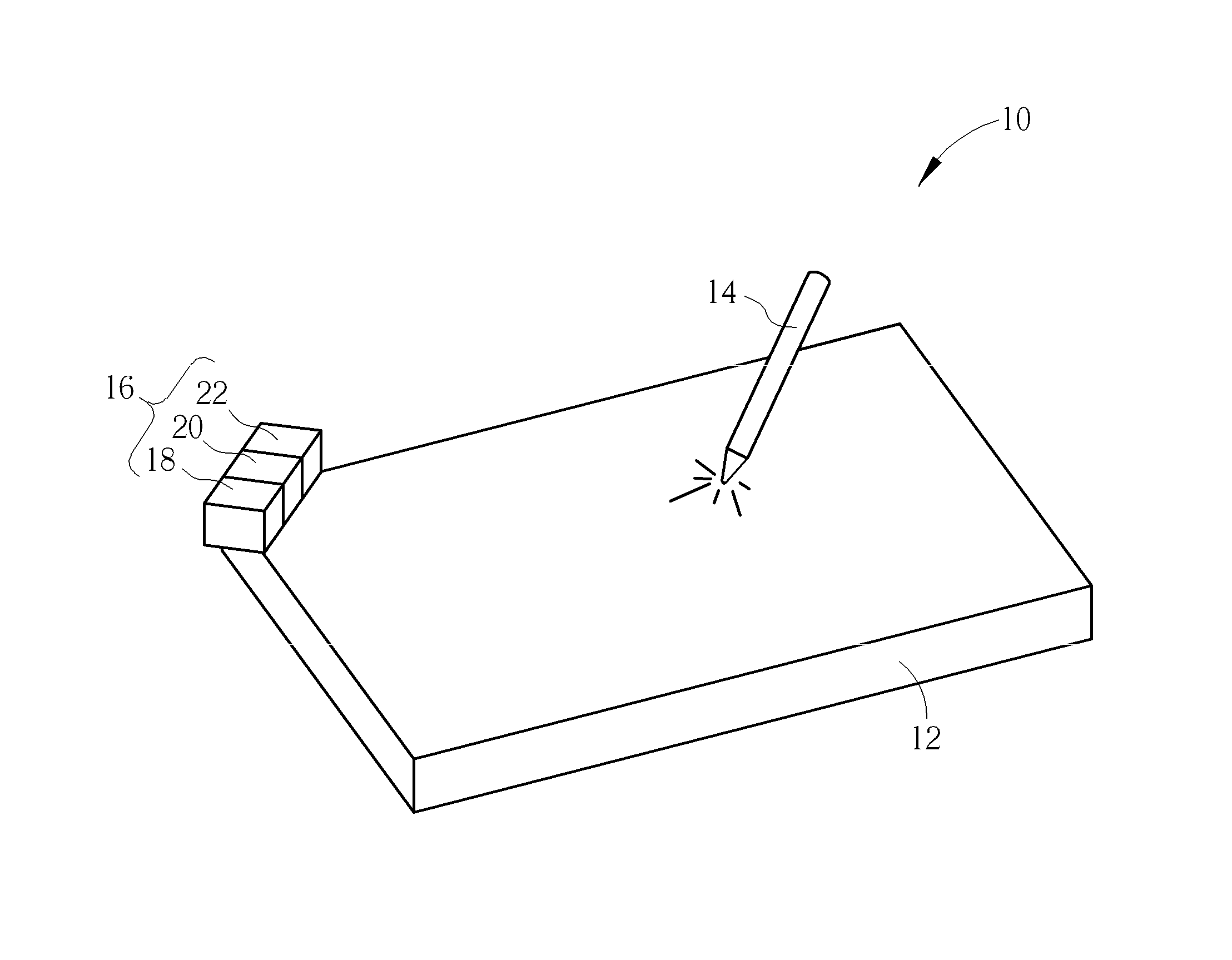
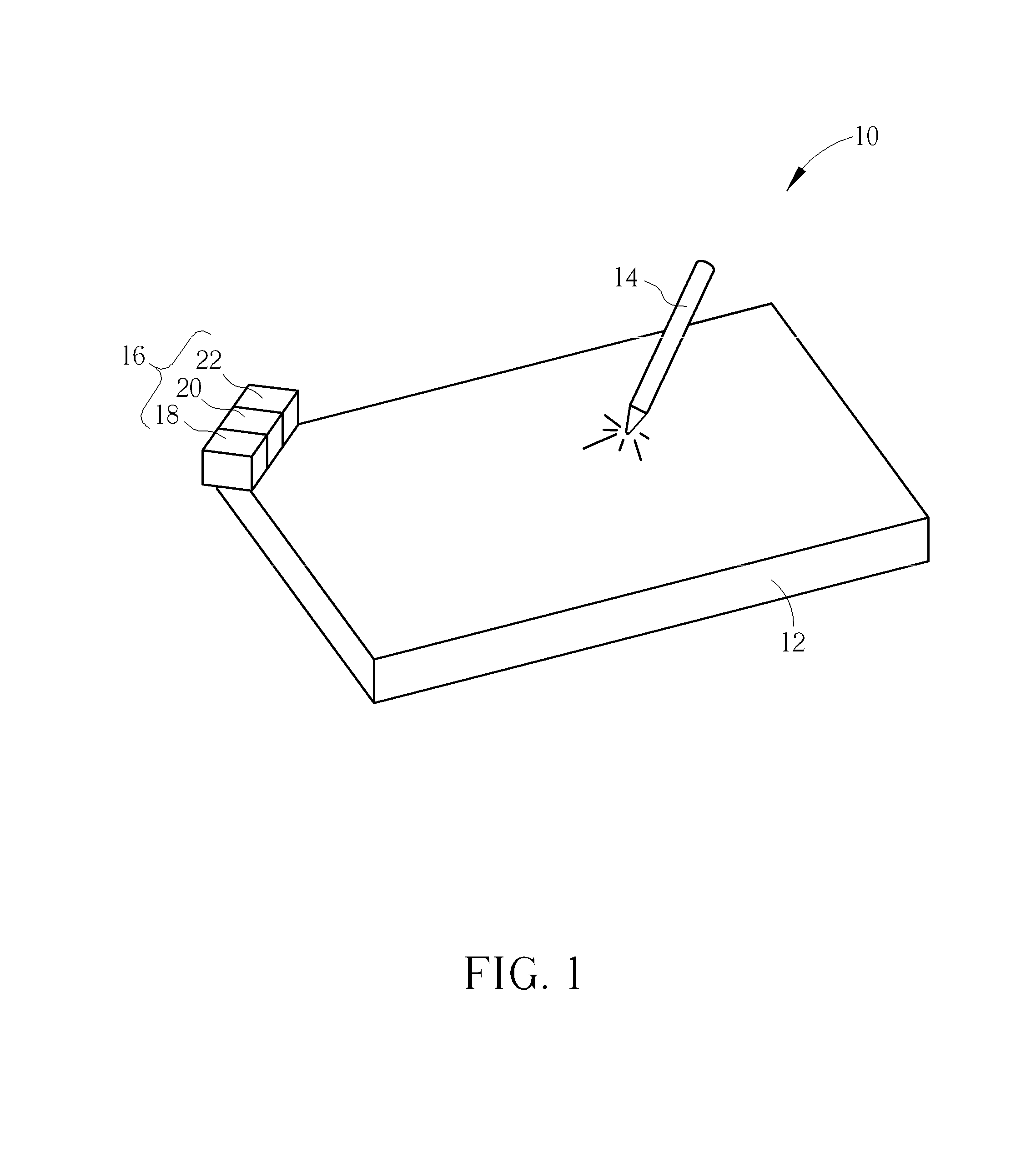
[0017]Please refer to FIG. 1. FIG. 1 is a diagram of an optical touch system 10 according to an embodiment of the present invention. The optical touch system 10 includes a panel 12, an active touch medium 14 and a coordinate positioning module 16. In the embodiment, the panel 12 can be a normal whiteboard or a displaying screen. The coordinate position module 16 is disposed on a corner of the panel 12, and the active touch medium 14 can be a stylus capable of emitting light. The active touch medium 14 can move above the surface of the panel 12 to input a command. The coordinate positioning module 16 can detect an optical signal S outputted from the active touch medium 14, and calculate track coordinates of the active touch medium 14 over the panel 12, so as to actuate the application program corresponding to the command according to the coordinates.

[0018]As shown in FIG. 1, the coordinate positioning module 16 includes an image detecting component 18 and a processor 20 (in another c...


PUM


Abstract

A method of detecting power of an active touch medium is disclosed in the present invention. The method includes capturing an image with an optical signal generated from the active touch medium, reading a first threshold value, comparing an intensity of the optical signal and the first threshold value, and executing a low power mode when the intensity of the optical signal is smaller than the first threshold value.

Description

BACKGROUND OF THE INVENTION[0001]1. Field of the Invention[0002]The present invention relates to a coordinate positioning module and a related optical touch system, and more particularly, to a coordinate positioning module having power detecting function and a related optical touch system, a method of detecting power of an active touch medium and a method of switching modes of the active touch medium.[0003]2. Description of the Prior Art[0004]A conventional optical touch apparatus includes two types of design. One type of the conventional optical touch apparatus utilizes the reflection bar or the light guide bar to detect a moving track of the inactive touch object, such as fingers, the stylus unable to emitting light, or any other touch medium, so as to calculate coordinates of the inactive touch object. The other type of the conventional optical touch apparatus utilizes the image detecting component to detect the style capable of emitting the light, and analyzes the coordinates of...

Claims


Application Information

Patent Timeline
IPC IPC(8): G06F3/042
CPCG06F3/042G06F3/0425G06F3/03542G06F3/033G06F3/03545G06F3/0386
Inventor LU, CHUN-YI
Owner PIXART IMAGING INC
Why Eureka
Try Eureka