Head suspension having actuator in which piezoelectric element is bonded with bonding tape, actuator and method of attaching piezolectric element with bonding tape

a piezoelectric element and actuator technology, applied in the direction of head support, record information storage, instruments, etc., can solve the problems of affecting the performance of the head suspension, so as to reduce the number of adhesive applying and hardening steps, and improve productivity

Active Publication Date: 2014-04-17
NHK SPRING CO LTD
View PDF6 Cites 5 Cited by
  • Summary
  • Abstract
  • Description
  • Claims
  • Application Information

AI Technical Summary

Benefits of technology

[0018]An object of the present invention is to provide a head suspension, an actuator, and a method of attaching a piezoelectric element to an actuator attaching part, capable of reducing the number of adhesive applying and hardening steps, correctly positioning the piezoelectric element, and preventing an adhesive from freely flowing.
[0023]According to the first aspect, the bonding tape bonds the piezoelectric element to the actuator attaching part and the adhesive fixes the bonded piezoelectric element to the actuator attaching part, to reduce the number of adhesive applying and hardening steps to one and surely position the piezoelectric element in the actuator attaching part by the bonding. In addition, the first aspect prevents the adhesive from penetrating into unintended gaps. Surely fixing the piezoelectric element to the actuator attaching part results in stabilizing the rigidity, spring load, and dynamic characteristics of the head suspension to precisely support the head.
[0024]According to the second aspect, the method uses the bonding tape to bond the piezoelectric element to the actuator attaching part of the head suspension and then applies the adhesive to fix the bonded piezoelectric element to the actuator attaching part. The method reduces the number of adhesive applying and hardening steps to one and surely positions the piezoelectric element in the actuator attaching part by the bonding, thereby improving productivity. The bonding tape restricts the flowing of the adhesive that is applied after bonding with the bonding tape, thereby preventing the adhesive from penetrating into unintended gaps. This results in stabilizing the rigidity, spring load, and dynamic characteristics of the head suspension. The bonding tape is easy to be handled for bonding the piezoelectric element to the actuator attaching part and using the bonding tape is achievable to improve productivity.
[0025]According to the third aspect, the bonding tape bonds the piezoelectric element to the actuator attaching part and the adhesive fixes the bonded piezoelectric element to the actuator attaching part, to reduce the number of adhesive applying and hardening steps to one and surely position the piezoelectric element in the actuator attaching part by the bonding. In addition, the third aspect prevents the adhesive from penetrating into unintended gaps. With the correctly fixed piezoelectric element, the actuator is capable of precisely driving, for example, a head of a head suspension.
[0026]According to the fourth aspect, the method uses the bonding tape to bond the piezoelectric element to the actuator attaching part of the actuator and then applies the adhesive to fix the bonded piezoelectric element to the actuator attaching part. The method reduces the number of adhesive applying and hardening steps to one and surely positions the piezoelectric element in the actuator attaching part by the bonding, thereby improving productivity. The bonding tape restricts the flowing of the adhesive that is applied after bonding with the bonding tape, thereby stabilizing the rigidity and other characteristics of the actuator. The bonding tape is easy to be handled for bonding the piezoelectric element to the actuator attaching part and using the bonding tape is achievable to improve productivity.

Problems solved by technology

These adhesive applying and hardening steps are time-consuming to deteriorate productivity.
If this happens, the rigidity, spring load, and dynamic characteristics of the head suspension will be spoiled or varied.

Method used


Image

  • Head suspension having actuator in which piezoelectric element is bonded with bonding tape, actuator and method of attaching piezolectric element with bonding tape
  • Head suspension having actuator in which piezoelectric element is bonded with bonding tape, actuator and method of attaching piezolectric element with bonding tape
  • Head suspension having actuator in which piezoelectric element is bonded with bonding tape, actuator and method of attaching piezolectric element with bonding tape

Examples


first embodiment

[0055] the bonding tape 27 is non-liquid and does not harden after the nonconductive adhesive 29 hardens. The bonding tape 27 may be one that hardens when the nonconductive adhesive 29 hardens.

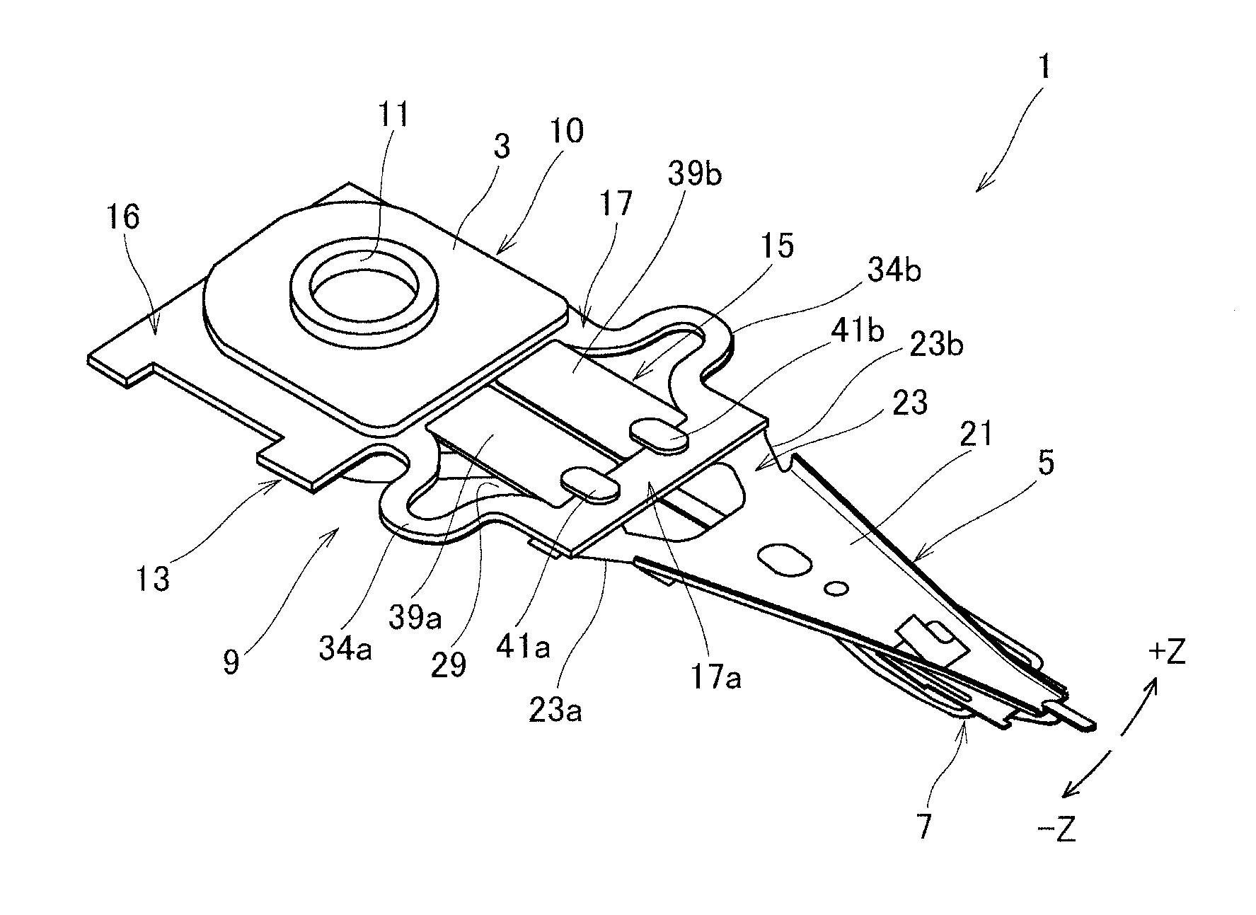
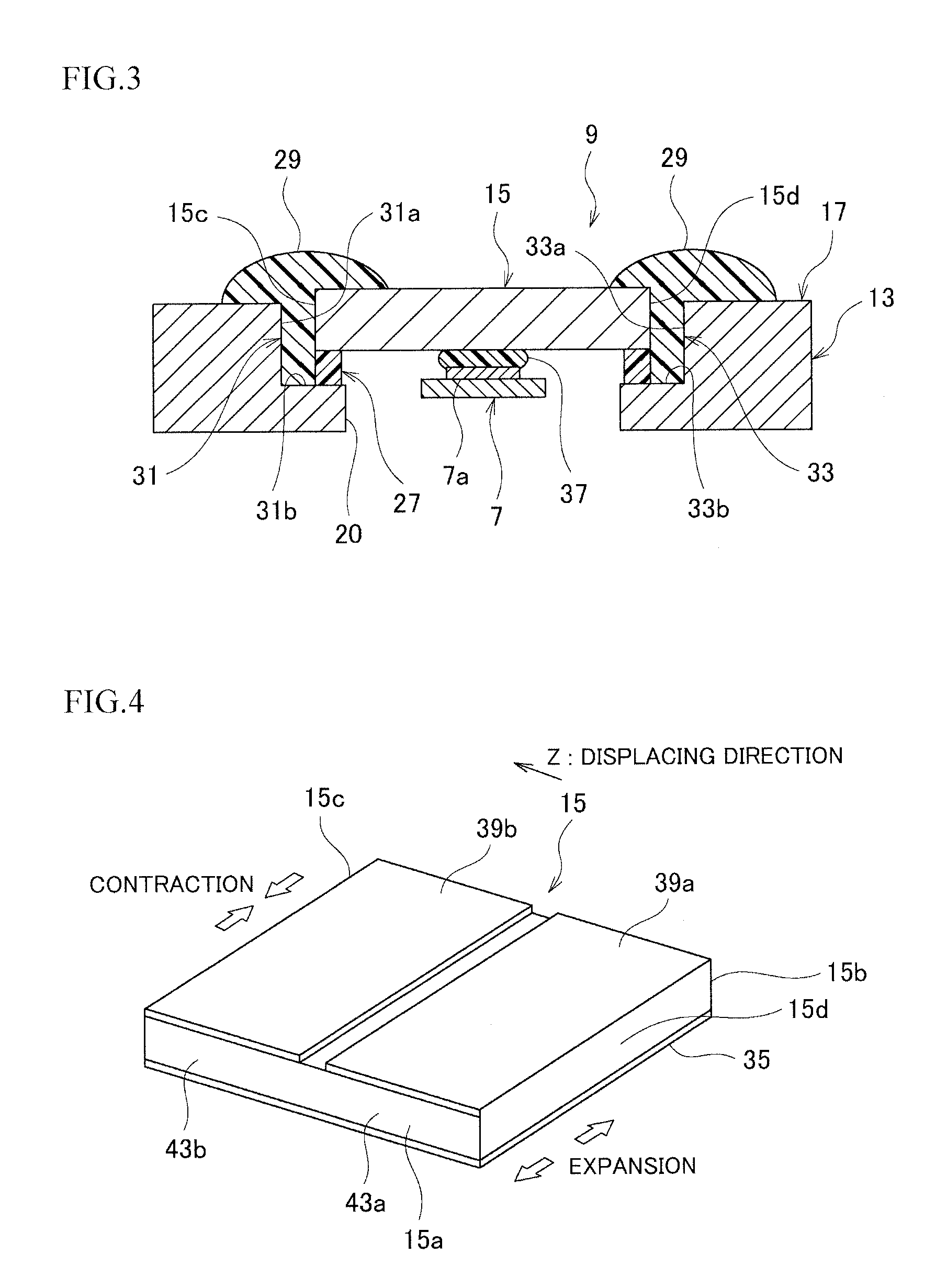
[0056]The contact 7a of the flexure 7 (hereinafter also referred to as “flexure contact 7a”) is bonded to a central part of the common electrode plate 35 of a first surface of the piezoelectric element 15 with conductive paste 37 such as silver paste that is a conductive adhesive. On a second surface opposite to the common electrode plate 35, the piezoelectric element 15 has a pair of electrode plates 39a and 39b that are connected to the front end 17a of the actuator attaching part 17 with respective conductive adhesives 41a and 41b as illustrated in FIG. 1.

[0057]As illustrated in FIG. 4, the piezoelectric element 15 is a flat plate having a rectangular shape and is made of a pair of piezoelectric materials 43a and 43b. On and over first surfaces of the piezoelectric materials 43a and 43b, th...

second embodiment

[0093] the bonding tape 27B has a central contact hole 27Ba to define and expose a contact on the piezoelectric element 15 and is bonded to the common electrode plate 35 of the piezoelectric element 15.

[0094]Attaching the piezoelectric element 15 to the actuator attaching part 17 is carried out in an order similar to FIGS. 6A to 6D. FIG. 10B corresponds to FIG. 6C and FIG. 10C to FIG. 6D. According to the second embodiment, the contact 7a of the flexure 7 is set in the through opening 20 and is bonded through the hole 27Ba of the bonding tape 27B to a central portion of the common electrode plate 35 of the piezoelectric element 15 with the conductive paste 37.

[0095]As a result, the conductive paste 37 on the flexure contact 7a is surrounded by an inner periphery of the hole 27Ba to prevent the conductive paste 37 from spreading or oozing out. If the bonding tape 27B is one that does not harden after the nonconductive adhesive 29 hardens, it will relax stress on the conductive paste ...

fourth embodiment

[0111] the piezoelectric element 15 is bonded to the support faces 31b and 33b of the actuator supports 31 and 33 of the actuator attaching part 17 with the bonding tape 27E like FIG. 6B. At this time, the contact 7a of the flexure 7 is not yet bonded to the piezoelectric element 15 in this example. The actuator attaching part 17 with the piezoelectric element 15 is inverted as illustrated in FIG. 13A.

[0112]The bonding tape 27E has a central contact hole 27Ea like that of FIG. 10A.

[0113]Conductive paste 37 is applied to a central part of the common electrode plate 35 of the piezoelectric element 15 and the contact 7a of the flexure 7 is set on the conductive paste 37 and is bonded to the common electrode plate 35 with the conductive paste 37 as illustrated in FIG. 13B. At this time, the conductive paste 37 on the flexure contact 7a is surrounded by the inner periphery of the hole 27Ea, and therefore, does not ooze out.

[0114]In this way, the fourth embodiment bonds the piezoelectric ...


PUM

PropertyMeasurementUnit
stressaaaaaaaaaa
voltageaaaaaaaaaa
viscoelasticaaaaaaaaaa

Abstract

A head suspension includes a base to be attached to a carriage, a load beam having a rigid part and a resilient part that connects the rigid part to the base, the load beam applying load onto a read / write head, a flexure attached to the load beam and supporting the head, an actuator attaching part located between the base and the head, and a piezoelectric element being deformable in response to a voltage applied thereto to move the head in a sway direction relative to the base. For the head suspension, it bonds the piezoelectric element with a bonding tape to the actuator attaching part and applies an adhesive to fix the piezoelectric element to the actuator attaching part.

Description

BACKGROUND OF THE INVENTION[0001]1. Field of the Invention[0002]The present invention relates to a head suspension having a piezoelectric element that deforms in response to an applied voltage, an actuator having such a piezoelectric element, and a method of attaching such a piezoelectric element to an actuator attaching part.[0003]2. Description of Related Art[0004]A head suspension is a device installed in, for example, a hard disk drive to write and read data on a hard disk of the hard disk drive. Such a head suspension may have an actuator in which a piezoelectric element is attached to an actuator attaching part.[0005]A head suspension, an actuator, and a method of attaching a piezoelectric element to an actuator attaching part according to a related art will be explained with reference to FIGS. 15A to 15F.[0006]FIGS. 15A to 15F are sectional views, in which FIG. 15A illustrates an actuator attaching part 103 and a contact 111a of a flexure 111, FIG. 15B illustrates a condition...

Claims


Application Information

Patent Timeline
Patent Type & Authority Applications(United States)
IPC IPC(8): G11B5/48
CPCG11B5/4873G11B5/4833G11B5/127
Inventor ARAI, MIKIO
Owner NHK SPRING CO LTD
Why Eureka
Try Eureka