
Parametric transducers and related methods

a technology of parametric transducers and related methods, applied in the field of parametric loudspeakers, can solve the problems of unable to meet the needs of commercial attempts to capitalize on this intriguing phenomenon, and the basic concepts integral to such technology, while relatively easy to implement and demonstrate, do not lend themselves to applications with relatively high volume outputs. achieve the effect of increasing outpu

Active Publication Date: 2014-04-17
TURTLE BEACH
View PDF6 Cites 14 Cited by
  • Summary
  • Abstract
  • Description
  • Claims
  • Application Information

AI Technical Summary

Benefits of technology

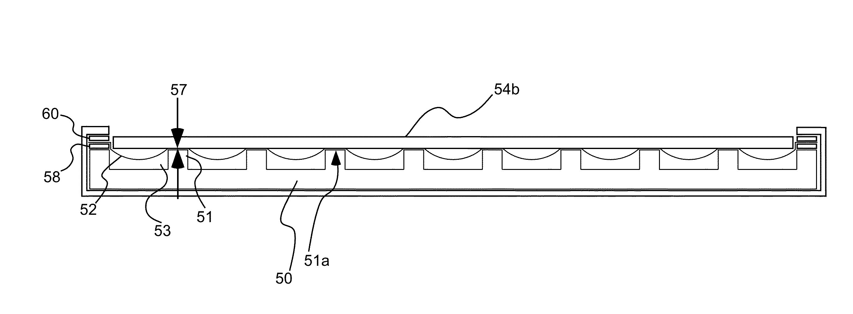
The invention provides a method for increasing the output of an ultrasonic emitter by attaching an ultrasonic material to a support member with support ribs and positioning a protective screen with a plurality of apertures atop the support ribs. This results in a substantially zero spacing between the ultrasonic material and the protective screen, which allows for increased output of ultrasonic energy.

Problems solved by technology

While the theory of non-linear transduction has been addressed in numerous publications, commercial attempts to capitalize on this intriguing phenomenon have largely failed.
Most of the basic concepts integral to such technology, while relatively easy to implement and demonstrate in laboratory conditions, do not lend themselves to applications where relatively high volume outputs are necessary.
As the technologies characteristic of the prior art have been applied to commercial or industrial applications requiring high volume levels, distortion of the parametrically produced sound output has resulted in inadequate systems.
These intense levels have often been greater than the physical limitations of the emitter device, resulting in high levels of distortion or high rates of emitter failure, or both, without achieving the magnitude required for many commercial applications.
While each of these techniques has proven to have some merit, they have not separately or in combination allowed for the creation of a parametric emitter system with high quality, low distortion and high output volume.
The present inventor has found, in fact, that under certain conditions some of the techniques described above may actually cause more measured distortion than does a basic system of like components without the presence of these prior art techniques.

Method used


Image

  • Parametric transducers and related methods
  • Parametric transducers and related methods
  • Parametric transducers and related methods

Examples


Embodiment Construction

[0021]Reference will now be made to the exemplary embodiments illustrated in the drawings, and specific language will be used herein to describe the same. It will nevertheless be understood that no limitation of the scope of the invention is thereby intended. Alterations and further modifications of the inventive features illustrated herein, and additional applications of the principles of the inventions as illustrated herein, which would occur to one skilled in the relevant art and having possession of this disclosure, are to be considered within the scope of the invention.

DEFINITIONS

[0022]As used herein, the singular forms “a” and “the” can include plural referents unless the context clearly dictates otherwise. Thus, for example, reference to “an emitter” can include one or more of such emitters.

[0023]As used herein, the term “substantially” refers to the complete or nearly complete extent or degree of an action, characteristic, property, state, structure, item, or result. For exa...


PUM


Abstract

An ultrasonic emitter comprises a support member operable to support an ultrasonic emittive material. The support member includes a plurality of support ribs. The ultrasonic emittive material is coupled to upper portions of the support ribs so as to be carried by the support member. A protective screen has a plurality of apertures formed therein, the protective screen being in contact with the ultrasonic emittive material atop the support ribs such that the spacing between the ultrasonic emittive material and the protective screen is substantially zero atop the support ribs.

Description

PRIORITY CLAIM[0001]Priority is claimed to U.S. Provisional Patent Application Ser. No. 61 / 625,801, filed Apr. 18, 2012, which is hereby incorporated herein by reference in its entirety.RELATED CASES[0002]This application is related to U.S. patent application Ser. No. 13 / 160,051, filed Jun. 14, 2011, which claims priority of U.S. Provisional Patent Application Ser. No. 61 / 354,533, filed Jun. 14, 2010, and which claims priority of U.S. Provisional Patent Application Ser. No. 61 / 445,195, filed Feb. 22, 2011, all of which are hereby incorporated herein by reference in their entirety.BACKGROUND OF THE INVENTION[0003]1. Field of the Invention[0004]The present invention relates generally to the field of parametric loudspeakers used to produce useful audible sound.[0005]2. Related Art[0006]Non-linear transduction, such as a parametric array in air, results from the introduction of sufficiently intense, audio modulated ultrasonic signals into an air column. Self demodulation, or down-conver...

Claims


Application Information

Patent Timeline
IPC IPC(8): H04B11/00
CPCH04B11/00H04R17/10H04R17/00H04R2217/03H04R1/023
Inventor NORRIS, ELWOOD G.
Owner TURTLE BEACH
Learn More