
Eureka
For R&D, Eureka makes reading and utilizing patents & technical documents easy.
Eureka AIR
Designed for self-driven R&D workflows. Generate viable solutions, solve complex R&D challenges, empower your innovation with AI.

Eureka Materials
Designed for material experts only. Revolutionize your material R&D, from search, analyze, to developing new materials.

TechResearch
Generate reliable direction feasibility study reports for your R&D in just a few steps.

TechSeek
Discover and master advanced knowledge NOW. Basics, ideas, possibilities, all at once.

TechMind
As an expert in R&D Theories, TechMind can generates customized viable solutions instantly.

TechRisk
Analyze your overall solution with one click, know your potential R&D risks in advance.

TechMonitor
Get weekly tech updates, stay abreast of the latest tech innovations and key insights.
High pressure gas to liquid process
- Summary
- Abstract
- Description
- Claims
- Application Information
AI Technical Summary
Benefits of technology
Problems solved by technology
Method used
Image

Examples
Example
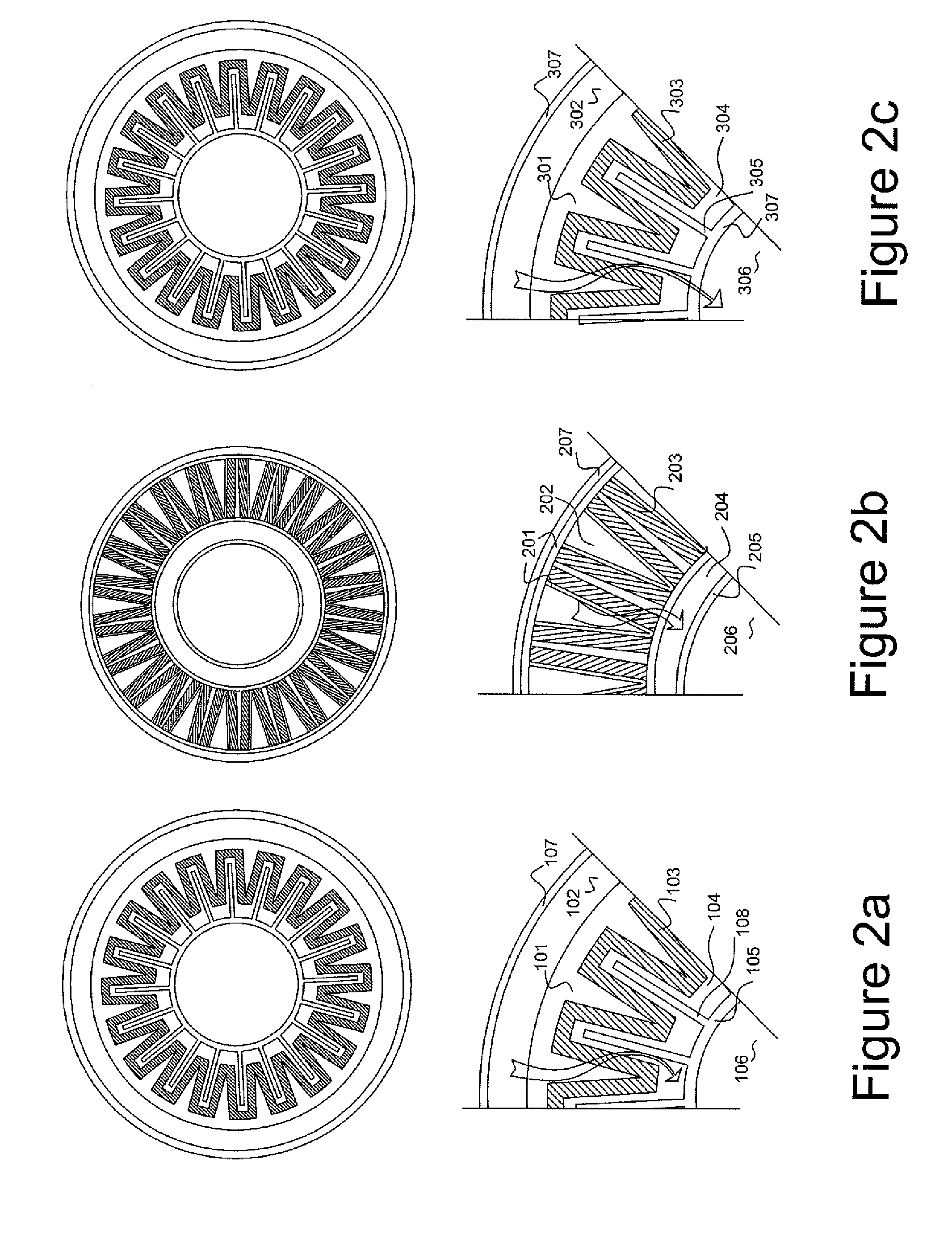
[0080]A second embodiment of the fixed bed of catalyst, also utilising forced flow through the catalyst pore structure in shown in FIG. 2b. In this arrangement the support of the catalyst, 201 is a porous metallic, thermally conducting structure which is in thermal contact with the heat transfer surface 207. The synthesis gas is introduced into chamber 202 and then forced by pressure through the catalyst bed 203 and porous or perforated metallic wall 201, collecting in chamber 204. A further heat transfer surface is provided, 205, within which heat transfer fluid 206 is circulating. A variation of this embodiment would be to operate in the absence of the heat transfer surface 107. This would have the benefit of making the reactor more compact, but reduces the heat transfer effectiveness of the reactor design.
Example
[0081]A third embodiment shown in FIG. 2c is a variation of the embodiment FIG. 2a. In this embodiment the wall 307 is porous or perforated allowing gas and liquid product to collect in chamber 306. The passage of gas into the chamber 306 agitates the liquid enhancing heat transfer and maintaining the even temperature of the surface 305. Furthermore, the gas fraction within the chamber 306 may be sufficient to lower the overall bulk density of the fluid such that recirculation of the hydrocarbon fluid may occur, either within the reactor or with an external loop in a similar manner to a thermosyphon mechanism of a heat exchanger of a boiler where the reduced overall density of liquid due to the presence of vapour spaces causes the fluid to be displace by cooler liquid continuous fluid. External cooling of the fluid could similarly be performed without the use of an external pump.
Example
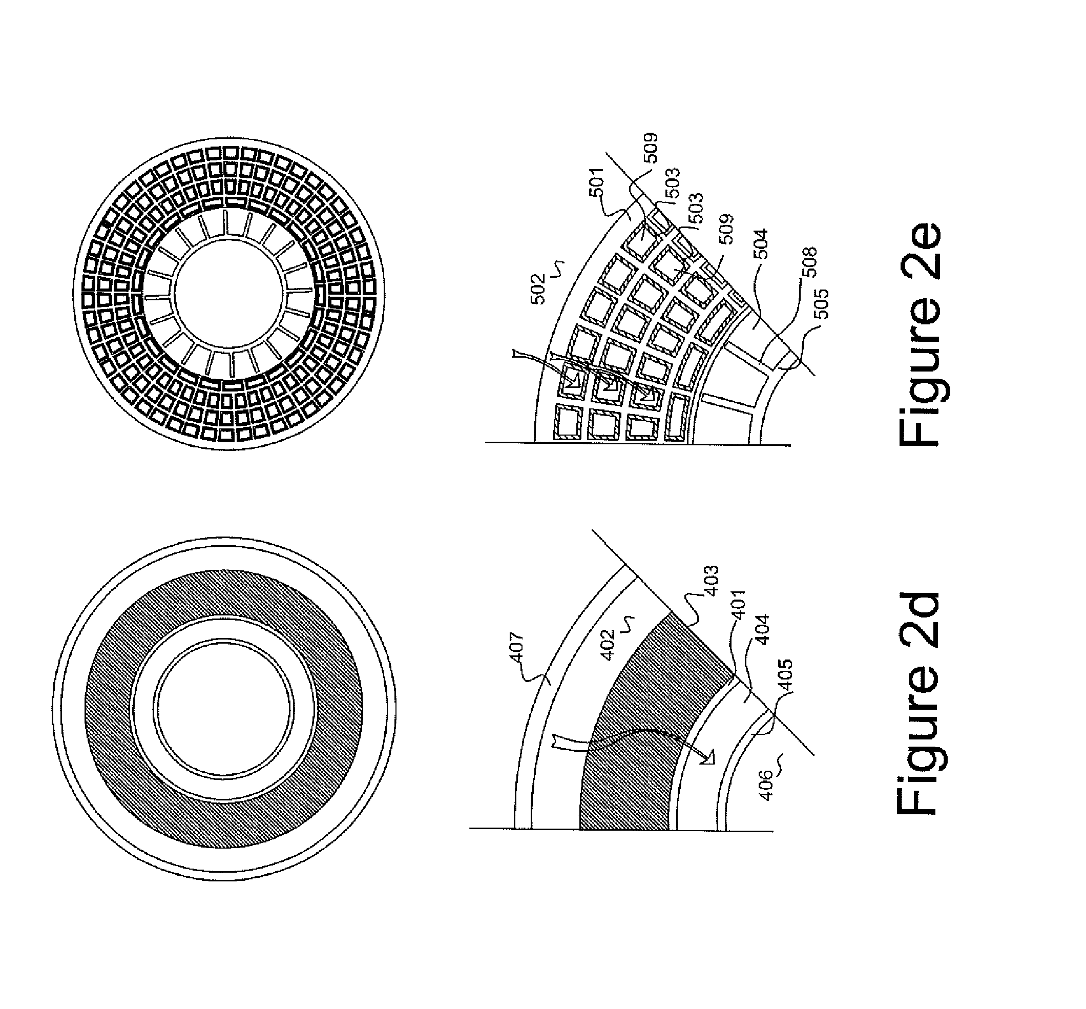
[0082]A fourth embodiment is shown in FIG. 2d in which a high permeability fixed bed of catalyst 403 is supported on a mechanically strong porous support, ceramic or metal 401. The synthesis gas passes from the external chamber 402 to the internal chamber 404. In this embodiment a heat transfer surface 405 and 407 is provided both internal and external to the fixed bed.
PUM
| Property | Measurement | Unit |
|---|---|---|
| Length | aaaaa | aaaaa |
| Length | aaaaa | aaaaa |
| Length | aaaaa | aaaaa |
Abstract
Description
Claims
Application Information
 - R&D Engineer
- R&D Manager
- IP Professional
- Industry Leading Data Capabilities
- Powerful AI technology
- Patent DNA Extraction
Browse by: Latest US Patents, China's latest patents, Technical Efficacy Thesaurus, Application Domain, Technology Topic, Popular Technical Reports.
© 2024 PatSnap. All rights reserved.Legal|Privacy policy|Modern Slavery Act Transparency Statement|Sitemap|About US| Contact US: help@patsnap.com