
Eureka
For R&D, Eureka makes reading and utilizing patents & technical documents easy.
Eureka AIR
Designed for self-driven R&D workflows. Generate viable solutions, solve complex R&D challenges, empower your innovation with AI.

Eureka Materials
Designed for material experts only. Revolutionize your material R&D, from search, analyze, to developing new materials.

TechResearch
Generate reliable direction feasibility study reports for your R&D in just a few steps.

TechSeek
Discover and master advanced knowledge NOW. Basics, ideas, possibilities, all at once.

TechMind
As an expert in R&D Theories, TechMind can generates customized viable solutions instantly.

TechRisk
Analyze your overall solution with one click, know your potential R&D risks in advance.

TechMonitor
Get weekly tech updates, stay abreast of the latest tech innovations and key insights.
Rotating device
- Summary
- Abstract
- Description
- Claims
- Application Information
AI Technical Summary
Benefits of technology
Problems solved by technology
Method used
Image

Examples
first embodiment
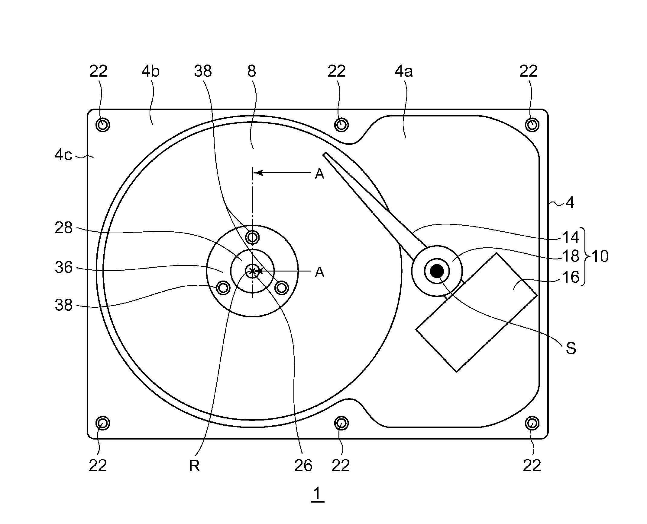
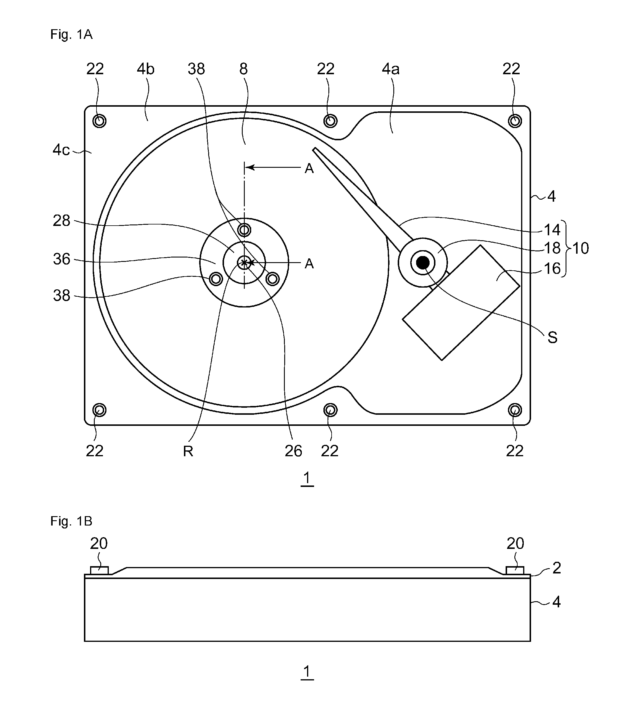
[0025]An overview of a rotating device according to the present embodiment is as shown below.
[0026]In the rotating device according to the present embodiment, a clamp screw hole for fixing a clamper, which is used to fix a recording disk to a hub, to the hub is formed in the hub. The clamp screw hole is formed as a through hole. Therefore, it becomes easy to form the clamp screw hole. Also, in the rotating device according to the present embodiment, a yoke is provided such that the yoke covers the base-side end portion of the clamp screw hole. Therefore, the amount of a vaporized lubricant flowing toward the recording disk through the clamp screw hole can be suppressed.
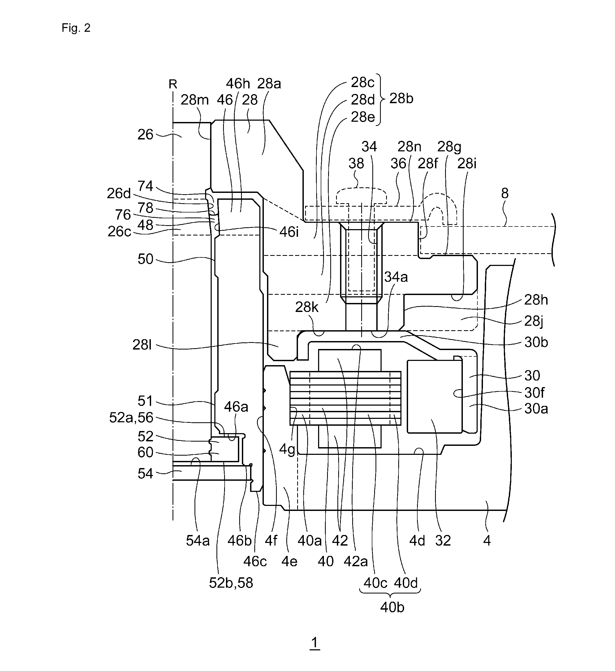
[0027]FIGS. 1A and 1B show a rotating device 1 according to the first embodiment. FIG. 1A is a top view of the rotating device 1. FIG. 1A shows the rotating device 1 without a top cover 2 in order to show the internal configuration of the rotating device 1. FIG. 1B is a side view of the rotating device 1.
[0028]The rot...
second embodiment
[0077]Main differences between the rotating device 1 according to the first embodiment and a rotating device 200 according to a second embodiment are the shape of a yoke and the shape of a hub.
[0078]FIG. 5 shows a section view of the rotating device 200 according to the second embodiment. FIG. 5 corresponds to FIG. 2.
[0079]A yoke 230 is formed by the press working of a magnetic material such as iron and is formed such that the thickness thereof is in a range of 0.2 mm to 1.0 mm. The yoke 230 has a shaft surrounding portion 230e that surrounds a shaft 26, a sleeve facing portion 230d that extends outward in the radial direction from the lower end of the shaft surrounding portion 230e and that faces the upper end 46d of a sleeve 46, a hub contacting portion 230c that extends downward from the sleeve facing portion 230d and that surrounds the sleeve 46, a cover portion 230b that extends outward in the radial direction from the lower end of the hub contacting portion 230c, and a magnet ...
third embodiment
[0083]A main difference between the rotating device 200 according to the second embodiment and a rotating device 300 according to a third embodiment is the shape of a yoke.
[0084]FIG. 6 shows a section view of the rotating device 300 according to the third embodiment. FIG. 6 corresponds to FIG. 5.
[0085]A yoke 330 has a shaft surrounding portion 330e, a sleeve facing portion 330d, a hub contacting portion 330c, a cover portion 330b, and a magnet holding portion 330a. In the present embodiment, the sleeve facing portion 330d extends outward in the radial direction from the upper end of the shaft surrounding portion 330e.
[0086]In the rotating device 300 according to the present embodiment, operations and effects are achieved that are similar to those achieved by the rotating device 200 according to the second embodiment.
PUM
 Abstract
Description
Claims
Application Information
 - R&D Engineer
- R&D Manager
- IP Professional
- Industry Leading Data Capabilities
- Powerful AI technology
- Patent DNA Extraction
Browse by: Latest US Patents, China's latest patents, Technical Efficacy Thesaurus, Application Domain, Technology Topic, Popular Technical Reports.
© 2024 PatSnap. All rights reserved.Legal|Privacy policy|Modern Slavery Act Transparency Statement|Sitemap|About US| Contact US: help@patsnap.com