

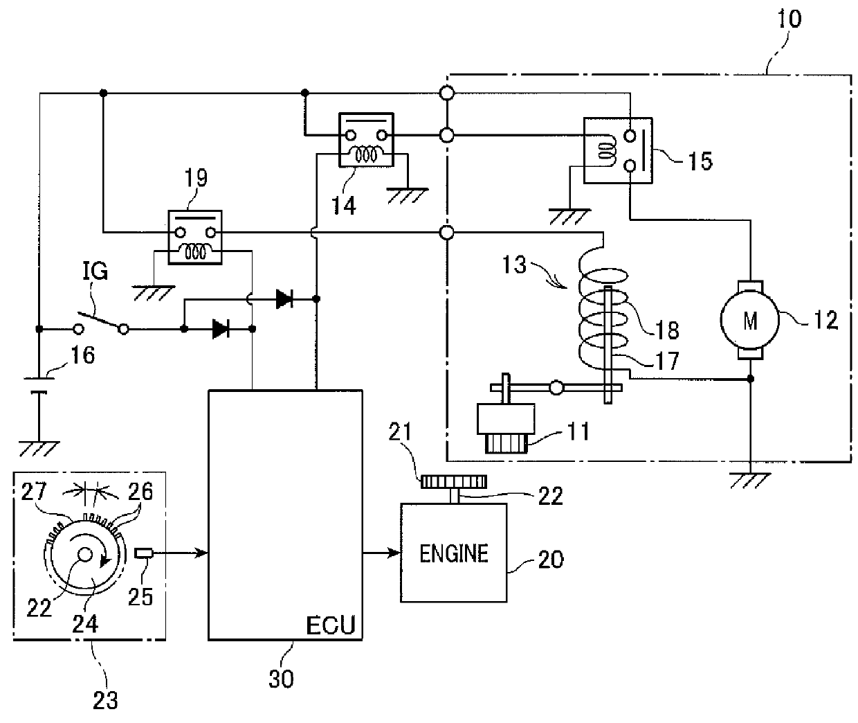
Engine control system designed to predict engine speed accurately
a technology of engine control and accurate prediction, which is applied in the direction of electric control, speed sensing governor, engine starter, etc., can solve the problems of increased mechanical noise or wear of the pinion or the ring gear, difficult to predict the time when an engine restart request is made, and large error in calculating the speed of the engine while the output sha
- Summary
- Abstract
- Description
- Claims
- Application Information
AI Technical Summary
Benefits of technology
Problems solved by technology
Method used
Image

Examples
second embodiment
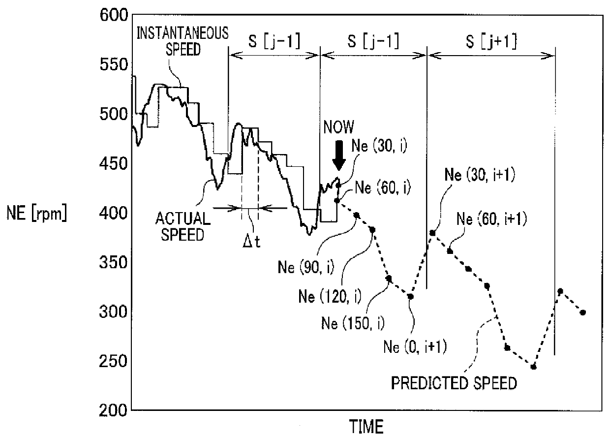
[0109]The engine control system of the second embodiment will be described below which is designed to predict the speed of the engine 20 during the reverse rotation of the engine 20 without use of the loss energy during the forward rotation of the engine 20.
[0110]Usually, an amount by which the output shaft (i.e., the crankshaft 22) of the engine 20 rotates in the reverse direction within an interval from the start of reversal of rotation of the crankshaft 22 until the rotation of the crankshaft 22 is returned to the forward direction depends upon an angular position of the crankshaft 22 at a given time (e.g., the reversal decision time tb or the time at which the speed of the engine 20 reaches zero) before the rotation of the engine 20 is changed to the reverse direction. Such an amount will also be referred to as a reverse rotation amount below. The peak of speed of the crankshaft 22 within a period of time in which the crankshaft 22 has first rotated by the reverse rotation amoun...
first embodiment
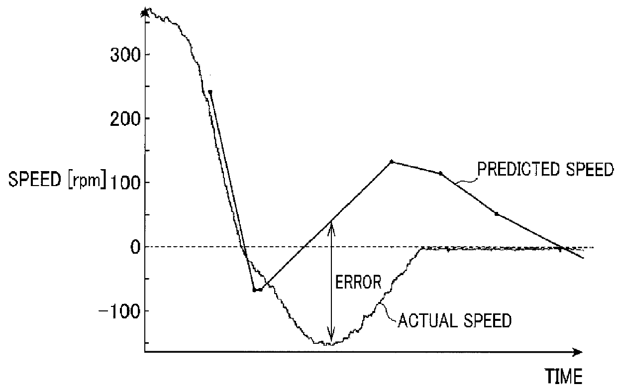
[0120]The engine control system is, as described above, designed to calculate the predicted value of the speed of the engine 20 during the reverse rotation of the engine 20 as a function of the crank angle position at a given time before the start of reversal of the rotation of the engine 20 based on the fact that the reverse rotation amount that is an amount by which the output shaft (i.e., the crankshaft 22) of the engine 20 rotates in the reverse direction immediately after the reversal of rotation of the engine 20 per unit time depends upon an angular position of the crankshaft 22 at the given time (e.g., the reversal decision time tb or the time at which the speed of the engine 20 reaches zero) before the start of reversal of rotation of the engine 20. In other words, the engine control system, like in the first embodiment, serves as either of the first calculator or the second calculator to predict a future speed of the engine 20 in the way different between during the forward...
PUM
 Abstract
Description
Claims
Application Information