
LED lighting apparatus having an adjustable light distribution

Active Publication Date: 2014-04-24
GIGATERA INC
View PDF4 Cites 2 Cited by
  • Summary
  • Abstract
  • Description
  • Claims
  • Application Information

AI Technical Summary

Benefits of technology

The present invention is for an LED lighting apparatus that can easily adjust and change the distribution of light patterns. It also has excellent heat dissipation characteristics, which can increase the lifespan of the LED lighting apparatus. The apparatus has a unique design that allows for convection of air to improve heat dissipation, which prevents overheating of the LED and its components.

Problems solved by technology

In this way, in the lighting apparatus using an LED according to the related art, since the light emission surface of the LED faces the ground, it is difficult to adjust a light distribution pattern of the LED.
Accordingly, in the lighting apparatus using an LED according to the related art, different housings should be made according to use of the lighting apparatus, and there is a problem in that it is impossible or very difficult to adjust the light distribution thereof.
In addition, since heat dissipation fins at an opposite side of the light emission surface of the LED according to the related art are disposed in parallel with the ground, air therein does not perform convection so that a heat dissipation effect is low and a lifespan of the LED is shortened.
Although there is a difference between light distribution patterns of a general street light and a tunnel lamp, it is difficult to arbitrarily form a light distribution pattern, and a lens for converting the light distribution patterns into a specific light distribution pattern is employed in order to solve the above-mentioned problems.
The lens corresponds to a factor of a LED light which increases a cost, and causes optical loss so as to decrease intensity of illumination.
When the lens is employed, since the intensity of illumination to be provided to the road surface decreases, more LEDs should be used to adjust the intensity of illumination of the road surface, which causes an increase in manufacturing costs and an increase in power consumption so as to deteriorate advantages of the LED light.

Method used


Image

  • LED lighting apparatus having an adjustable light distribution
  • LED lighting apparatus having an adjustable light distribution
  • LED lighting apparatus having an adjustable light distribution

Examples


Embodiment Construction

[0031]Hereinafter, an LED lighting apparatus capable of adjusting light distribution according to embodiments of the present disclosure will be described in detail with reference to the accompanying drawings.

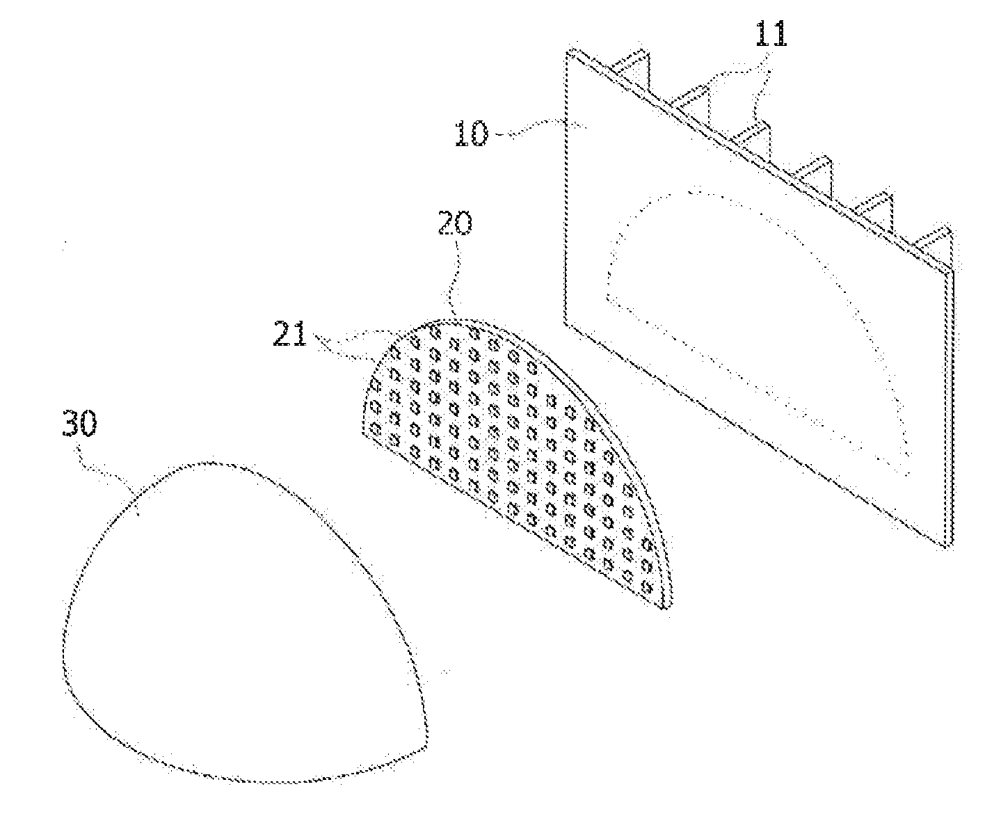
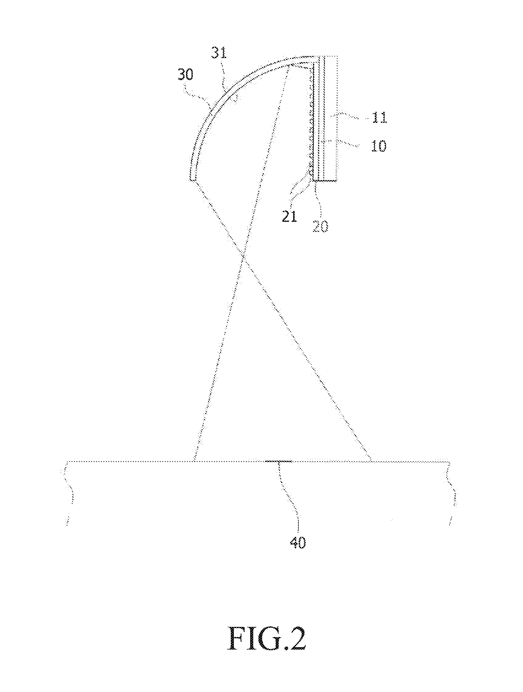
[0032]FIG. 1 is an exploded perspective view showing an LED lighting apparatus capable of adjusting light distribution according to an embodiment of the present disclosure, and FIG. 2 is a sectional view showing a coupled state of the LED lighting apparatus of FIG. 1.

[0033]Referring to FIGS. 1 and 2, an LED lighting apparatus capable of adjusting light distribution according to an embodiment of the present disclosure includes a support panel 10, which is shaped like a semicircular disc and has a rear surface having vertically-elongated heat dissipation fins 11, a substrate 20 coupled to a front surface of the support panel 10, a plurality of LEDs 21 being mounted to the substrate 20, and a reflection portion 30 fixed to the support panel 10 and having a curved reflection surface...


PUM


Abstract

An LED lighting apparatus having adjustable light distribution comprises: a support panel on which a plurality of heat dissipation fins are disposed on a back surface thereof, the support panel providing a parallel front part which is not parallel to the ground; a board on which a plurality of LEDs are mounted, and being coupled to said front part of the support panel; and a reflection part fixed to the support panel so as to be disposed on the front surface of said substrate, and reflecting light emitted from said plurality of LEDs to provide a curved reflection surface which forms light distribution patterns on the ground. The light emission surface of the LED is not disposed parallel to the ground. The light emitted from the LED is distributed through the reflection part having a curved surface reflecting the light emitted from the LED toward the ground.

Description

CROSS-REFERENCE TO RELATED APPLICATIONS[0001]This application is a continuation application of International Application No. PCT / KR2012 / 003280 filed on Apr. 27, 2012, which claims priority to Korean Application No. 10-2011-0047682 filed on May 20, 2011 and Korean Application No. 10-2011-0097486 filed on Sep. 27, 2011, which applications are incorporated herein by reference.TECHNICAL FIELD[0002]The present disclosure relates to an LED lighting apparatus capable of adjusting light distribution, and more particularly, to an LED lighting apparatus capable of adjusting light distribution in which LEDs are disposed vertically and a light distribution pattern thereof can be adjusted according to the position.BACKGROUND ART[0003]In general, in a lighting apparatus using an LED, such as a street light, a decoration light, and a security light, a substrate thereof to which the LED is mounted is disposed in parallel with the ground. Of course, although a structure in which an installation angl...

Claims


Application Information

Patent Timeline
IPC IPC(8): F21K99/00
CPCF21K9/58F21V7/0008F21W2131/103F21V29/75F21V29/763F21Y2115/10F21V7/0058F21V17/002F21V3/02F21V21/30F21W2121/00F21Y2113/00F21Y2105/18F21V29/76
Inventor KIM, DUK-YONG
Owner GIGATERA INC
Learn More