
System, Apparatus, and Method for Automatically Controlling a Locomotive

a technology of automatic control and control system, applied in the field of interface for manual controller and locomotive, can solve the problems of increased speed or high in-train force, manual control control control settings may not match the computer-controlled system settings when it is disengaged, and undesired acceleration or braking action,

Active Publication Date: 2014-04-24
WABTEC HLDG CORP
View PDF11 Cites 26 Cited by
  • Summary
  • Abstract
  • Description
  • Claims
  • Application Information

AI Technical Summary

Benefits of technology

The present invention provides systems, apparatus, and methods for automatically controlling a locomotive by interfacing with a manual control, an automatic control system, and a locomotive control system. The invention addresses certain drawbacks and deficiencies in known automatic control systems. The technical effects of the invention include improved safety and efficiency in controlling the locomotive, as well as increased operational flexibility and reliability.

Problems solved by technology

This implementation poses a problem in that, when a computer controls the throttle and brake systems and an operator is allowed to disengage the computer-controlled system, the control settings of the manual controls may not match the computer-controlled system settings when it is disengaged.
This mismatch of control settings can cause a number of problems, including an undesired jump up or down in a throttle notch, resulting in an undesired acceleration or braking action.
An undesired jump up of a throttle notch may result in increased speed or high in-train forces.
An undesired jump down in a throttle notch may be problematic if the train is climbing a steep grade, since a sudden loss of power could stall the train on the grade.
Further, if the dynamic brake or independent brake settings do not match the computer-controlled system settings, there may be a reduction in braking force that causes an undesired increase in speed.
Since neither the dynamic brake nor independent brake have detents in the handle position, it is difficult to indicate to the crew where to place the handle when disengaging.
If the brake handle setting does not match the computer-controlled automatic brake setting, there may be an undesired release of the train air brakes.
This could be an undesirable situation because it reduces the brake pipe to a low level and could reach the point of not being able to command further reductions.

Method used


Image

  • System, Apparatus, and Method for Automatically Controlling a Locomotive
  • System, Apparatus, and Method for Automatically Controlling a Locomotive
  • System, Apparatus, and Method for Automatically Controlling a Locomotive

Examples


Embodiment Construction

[0018]For purposes of the description hereinafter, the terms “end”, “upper”, “lower”, “right”, “left”, “vertical”, “horizontal”, “top”, “bottom”, “lateral”, “longitudinal” and derivatives thereof shall relate to the invention as it is oriented in the drawing figures. However, it is to be understood that the invention may assume various alternative variations and step sequences, except where expressly specified to the contrary. It is also to be understood that the specific devices and processes illustrated in the attached drawings, and described in the following specification, are simply exemplary embodiments of the invention. Hence, specific dimensions and other physical characteristics related to the embodiments disclosed herein are not to be considered as limiting.

[0019]As used herein, the terms “communication” and “communicate” refer to the receipt or transfer of one or more signals, messages, commands, or other type of data. For one unit or component to be in communication with ...


PUM


Abstract

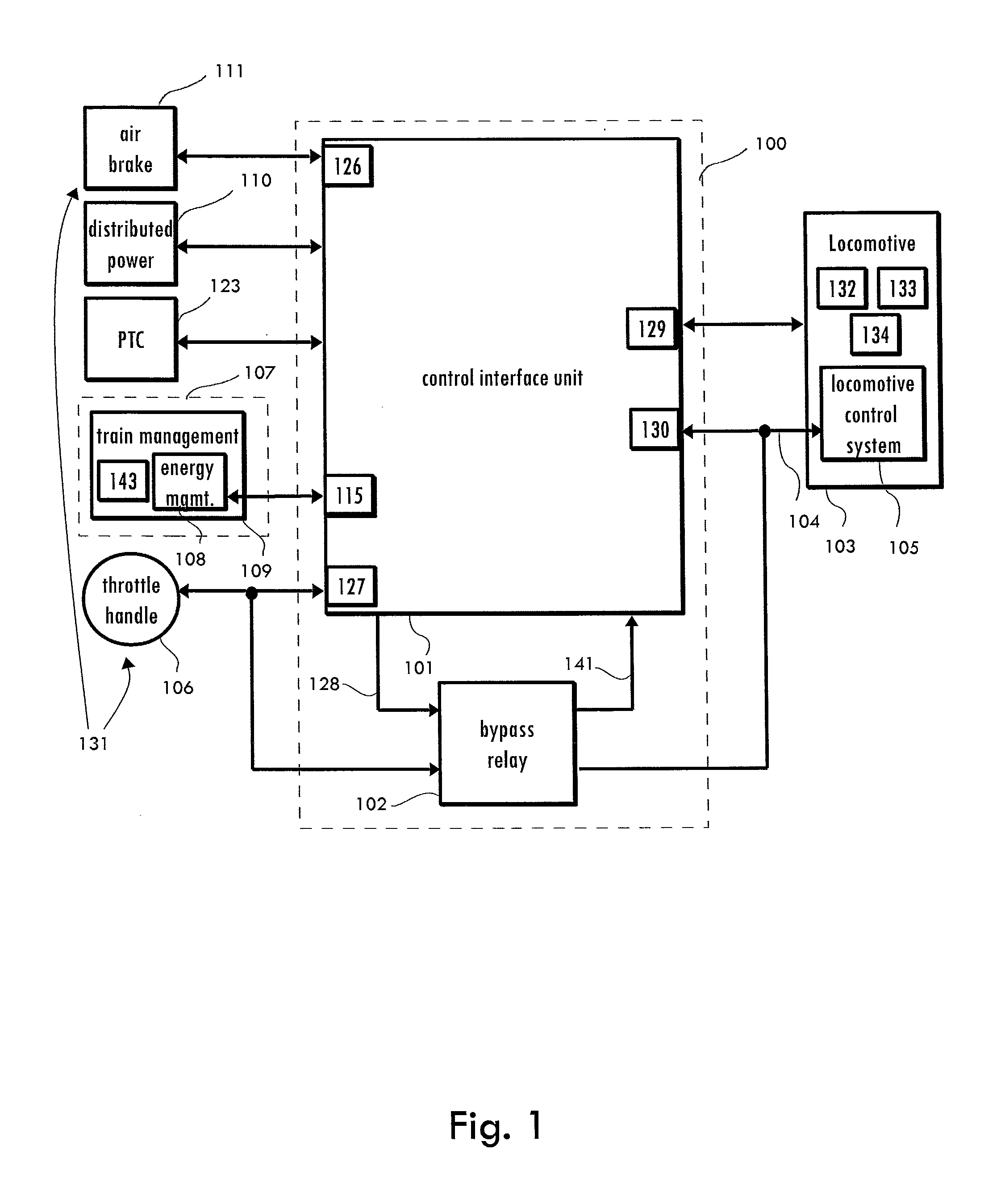
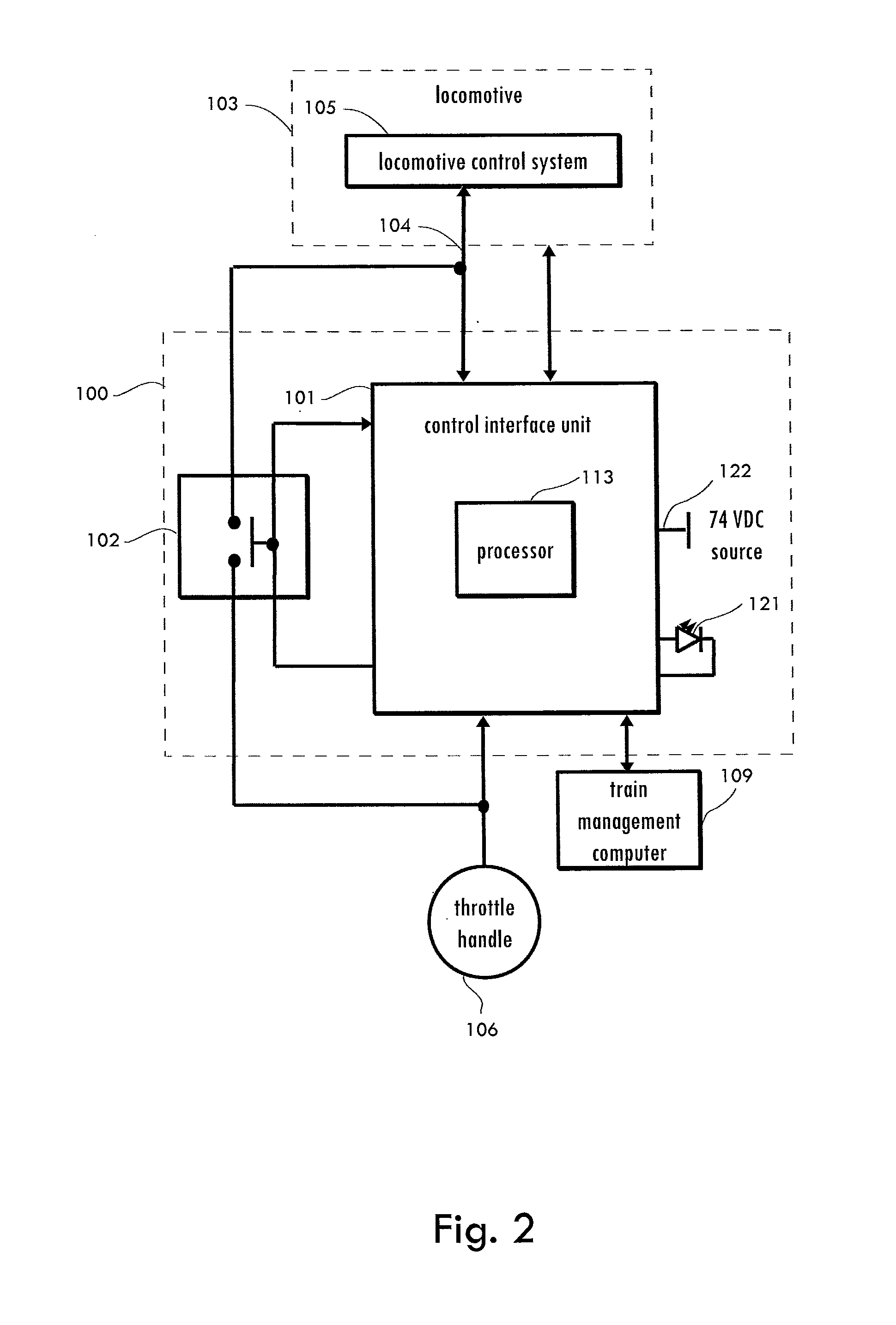
A system, method, and apparatus for automatically controlling a locomotive include a control interface unit configured to receive input from at least one manual control, receive input from an automatic control system, and transmit commands to a locomotive control system, wherein the commands are based at least partially on the input received from the automatic control system. A bypass relay may also be provided to enable and disable communication between the at least one manual control and the locomotive control system.

Description

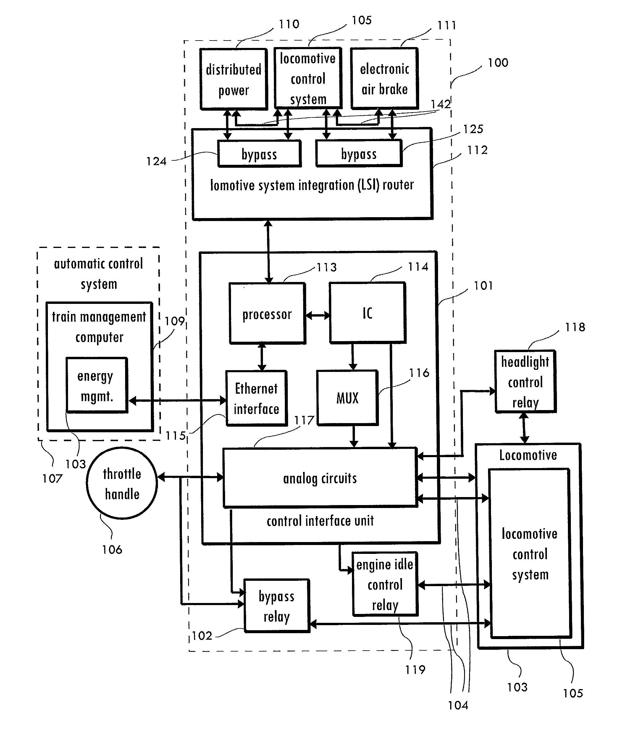
BACKGROUND OF THE INVENTION[0001]1. Field of the Invention[0002]This invention relates generally to an interface for a manual controller and a locomotive and, more specifically, to a system, apparatus, and method for controlling a locomotive with an automatic control system.[0003]2. Background of the Invention[0004]Railroads are beginning to pursue locomotive “cruise control” systems for operating locomotives. These systems will require a crew member to engage or disengage the system and will also require a computer to drive the throttle, dynamic brake, and air brake systems. These systems may be implemented in, for example, a lead locomotive of a train or a pusher locomotive. In these existing systems, a crew member would normally be present with a computer-controlled system that would have a need to control the throttle and brake of the locomotive.[0005]This implementation poses a problem in that, when a computer controls the throttle and brake systems and an operator is allowed t...

Claims


Application Information

Patent Timeline
Patent Type & Authority Applications(United States)
IPC IPC(8): B61C17/12
CPCB61C17/12B60L1/003B60L3/0069B60L3/04B60L7/26B60L9/04B60L9/12B60L9/22B60L9/28B60L2200/26B60L2240/12B60L2250/10B60L2250/16B60L2250/24Y02T90/16B61L15/0063B61L27/04B61L15/0036B61L15/0081B61L15/009B61L15/0062Y02T30/00
Inventor KERNWEIN, JEFFREY D.GILLEN, DONALD J.KLEMANSKI, RICHARD S.ROUSE, SHAWN D.SOLLARS, SCOTT A.
Owner WABTEC HLDG CORP
Learn More