
Method for modeling a reservoir using 3D multiple-point simulations with 2d training images

a reservoir and multiple-point simulation technology, applied in the field of reservoir modeling, can solve the problems of insufficient geological features, histogram and variogram, and algorithm only reproducing up to 2-point statistics, and iterative process creating problems,

Inactive Publication Date: 2014-04-24
CONOCOPHILLIPS CO
View PDF7 Cites 14 Cited by
  • Summary
  • Abstract
  • Description
  • Claims
  • Application Information

AI Technical Summary

Benefits of technology

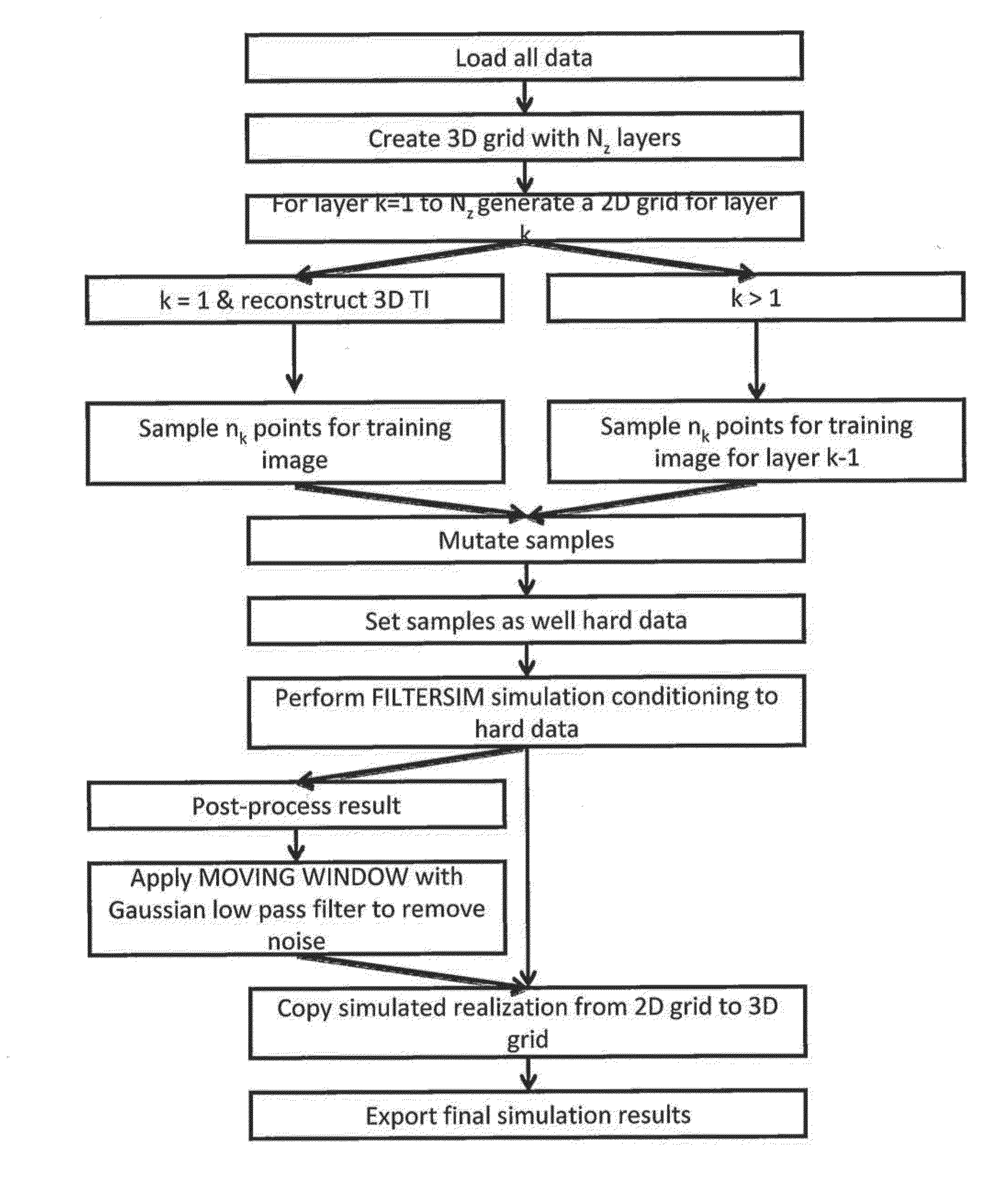
The patent text describes two methods for modeling a reservoir. The first method involves creating a 3D grid with multiple layers, creating a 2D grid for each layer, sampling the data from the 2D grid, and conditioning the data using a filter-based simulation. The second method involves receiving and loading data, creating a 3D grid with multiple layers, getting target facies proportions, sampling the data from the 2D grid, performing a single normal equation simulation to condition the data, and copying the simulation from the 2D grid to the 3D grid. The technical effect of these methods is to improve the accuracy and efficiency of reservoir modeling, allowing for more precise and accurate analysis of oil and gas reservoirs.

Problems solved by technology

However, these algorithms only reproduce up to 2-point statistics, histogram and variogram, which are not sufficient to generate complex geological features, such as lobes and channels.
However, the iterative process creates issues when the well spacing is smaller than the object size.
This situation gets worse with dense wells, 2D or 3D soft data, and other exhaustive information.
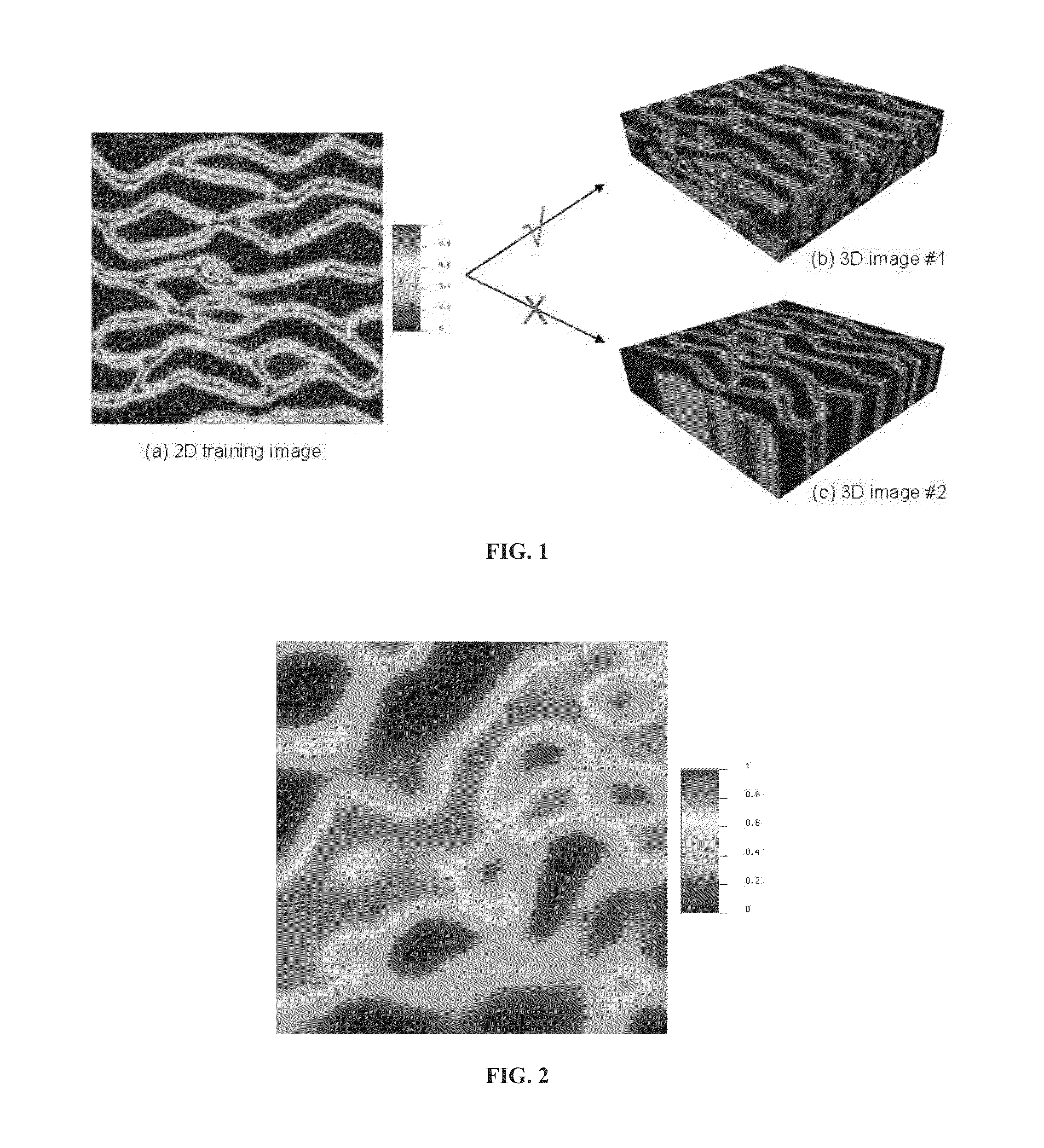
How to generate a 3D TI with a 2D map and how to simulate 3D mps models from a 2D TI become challenging for geoscientists.
In general, these methods require laborious operations and are very time consuming, hence are not suitable for the routine applications.
The main drawback with the statistics-based technique is the difficulty to reproduce the long range connectivity of interested variables.
However, process-based algorithms encounter difficulties when the sedimentation process becomes complex and / or involved irregular object shapes, for example the carbonate system.

Method used


Image

  • Method for modeling a reservoir using 3D multiple-point simulations with 2d training images
  • Method for modeling a reservoir using 3D multiple-point simulations with 2d training images
  • Method for modeling a reservoir using 3D multiple-point simulations with 2d training images

Examples


example

[0074]A four facies training image in FIG. 16 was used to simulate the distribution of channels, levees and ellipse drops in the mud background. The simulation grid was 200×200×10 in size. Each 2D SNESIM simulation was run with a radial search template containing 60 nodes and five multiple grids. During the simulation, ⅓ of the identified geo-bodies were removed from the conditioning data list.

[0075]One final 3D realization using the method is depicted in FIG. 17(a), which shows good vertical connectivity's for all foreground facies with some variations from one layer to another as seen from the different thicknesses of the geo-objects. For comparison, FIG. 17(b) gives one SNESIM realization simulated directly with the 2D TI, which depicts the strong layering effect as seen from the poor vertical continuities of the simulated geo-objects.

Variables

[0076]G=3D grid

[0077]N=cell dimension

[0078]k=layer index

[0079]n=number of sample

[0080]r=regular grid

[0081]int=interval


PUM


Abstract

A method for modeling a reservoir is described. One example of a method for modeling a 3D reservoir involves using multiple-point simulations with 2D training images.

Description

CROSS-REFERENCE TO RELATED APPLICATIONS[0001]This application is a non-provisional application which claims benefit under 35 USC §119(e) to U.S. Provisional Application Ser. No. 61 / 716,050 filed Oct. 19, 2012, entitled “METHOD FOR MODELING A RESERVOIR USING 3D MULTIPLE-POINT SIMULATIONS WITH 2D TRAINING IMAGES,” which is incorporated herein in its entirety.FIELD OF THE INVENTION[0002]This invention relates to a method for modeling a reservoir. More particularly, a method for modeling a 3D reservoir using multiple-point simulations with 2D training images.BACKGROUND OF THE INVENTION[0003]In the oil and gas industry, flow simulations are widely used for predicting the reservoir performance, which in many cases is controlled by the distribution of reservoir properties, such as facies, porosity and permeability.[0004]The variogram-based algorithms, e.g., SGSIM (Sequential Gaussian Simulation) and SISIM (Sequential Indicator Simulation), generate petrophysical distributions pixel-by-pixe...

Claims


Application Information

Patent Timeline
IPC IPC(8): G01V99/00
CPCG01V99/005G01V20/00
Inventor WU, JIANBINGLIU, YONGSHE
Owner CONOCOPHILLIPS CO
Learn More