
Image recognizing apparatus and method

a technology of image recognition and apparatus, applied in the field of image recognition apparatus and method, can solve the problems of reducing both search time and false detection, long search time, and high probability of making a false detection, and achieve the effect of improving image processing speed

Inactive Publication Date: 2014-05-01
ELECTRONICS & TELECOMM RES INST
View PDF3 Cites 7 Cited by
  • Summary
  • Abstract
  • Description
  • Claims
  • Application Information

AI Technical Summary

Benefits of technology

The present invention provides an image recognizing apparatus and method that can detect the size of target objects in an image and remove unnecessary areas without needing to calibrate the camera's position. This reduces the time needed for image processing and improves the speed of identifying target objects.

Problems solved by technology

However, such a recognition scheme has problems that it takes a long time to search for the target objects, and it has a high probability to make a false detection.
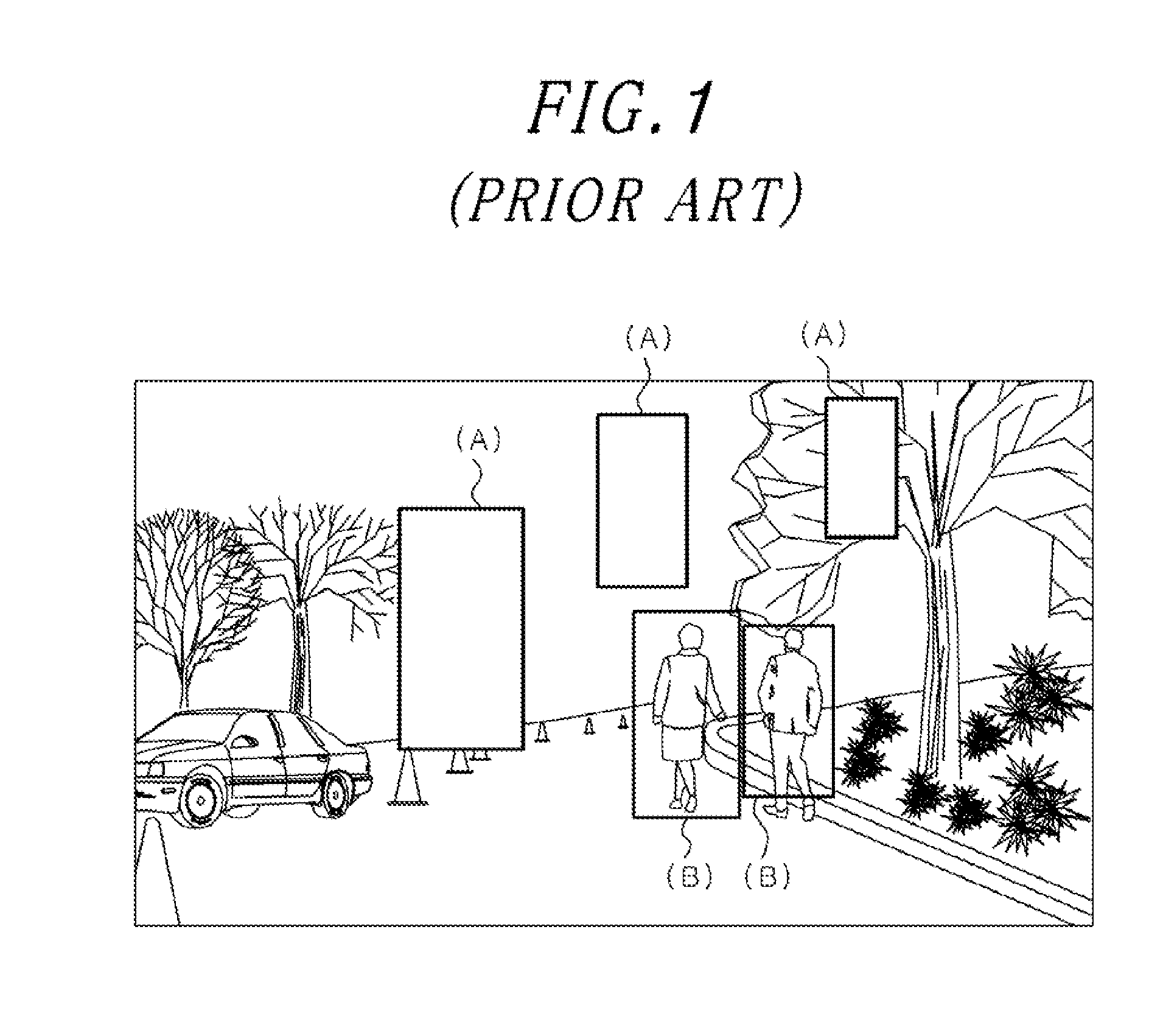
The image recognizing apparatus then skips over the abnormal candidate areas ‘A’ and tries to recognize only normal candidate areas ‘B’, resulting in reducing both the search time and false detections.
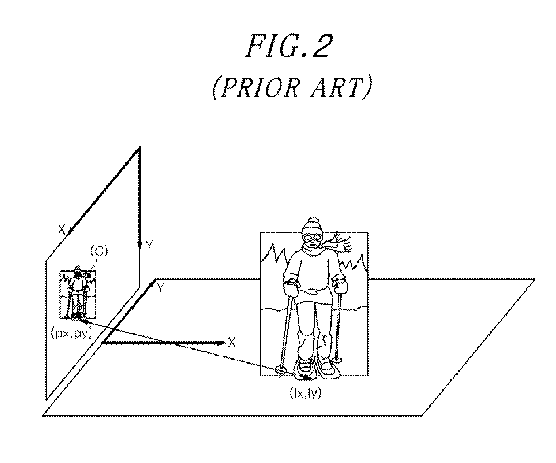
As described above, conventional image recognizing apparatus employs a method to confine the search region using the homography matrix H. However, calculating the homography matrix H and the focal length of the camera requires the use of additional tools and associated background knowledge on camera calibration, which leads to a long development time.
Further, the method to confine the search region using the homography matrix H is not applicable depending on circumstances.
Further, the method of utilizing the homography matrix H has a limitation in reflecting the size deviation of the target object and the recognition error of the vision-based recognition system effectively.
Therefore, if the allowable range of stature of pedestrian is set between 1 meter to 2 meter, it will be too restrictive to detect pedestrians far away from the camera because several pixels of error in homography will falsely reject true candidate regions.
On the contrary, if the detection range is set wide in order to cope with homography error, it will be too loose for close pedestrians.
Thus, it is difficult to control the search space effectively by using homography.

Method used


Image

  • Image recognizing apparatus and method
  • Image recognizing apparatus and method
  • Image recognizing apparatus and method

Examples


Embodiment Construction

[0031]Detailed description of the present invention will be described below with reference to the accompanying drawings illustrating specific embodiments of the present invention. These embodiments are described in detail so that those skilled in the art can easily practice the present invention. It should be understood that various embodiments of the present invention are different from each other, but need not be mutually exclusive. For example, a particular shape, structure and properties that are described herein and are related to one embodiment of the present invention may be implemented with other embodiments without departing the scope of the present invention. Further, it should be understood that the location and arrangement of the individual component in the embodiments may be changed without departing the scope of the present invention. Therefore, the detailed description below is rather than those that try to take as a limiting sense if it is explained properly, the sco...


PUM


Abstract

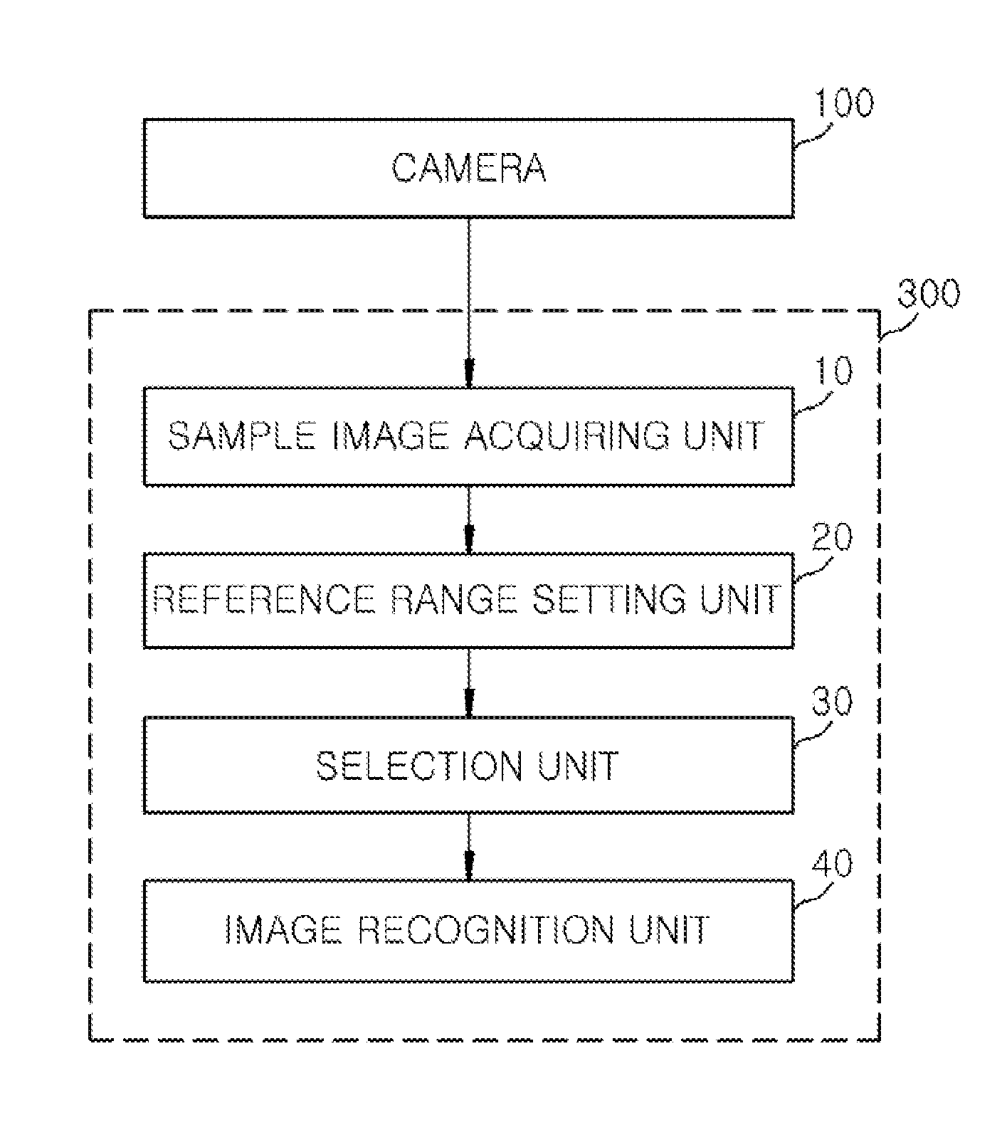
An image recognizing apparatus includes a sample image acquiring unit configured to acquire a sample image having one or more target objects therein from a camera; and a reference range setting unit configured to calculate image locations and image heights for the respective target objects from the sample image and set a reference range of the image heights depending on the image positions. Further, the image recognizing apparatus includes a selection unit configured to determine whether a candidate area of each target object in the sample image acquired by the camera falls within the reference range to select an effective candidate area.

Description

CROSS-REFERENCE TO RELATED APPLICATION(S)[0001]The present invention claims priority of Korean Patent Application No. 10-2012-0122555, filed on Oct. 31, 2012, which is incorporated herein by reference.FIELD OF THE INVENTION [0002]The present invention relates to an image recognizing apparatus and method; and more particularly, to an image recognizing apparatus and method, which detects the effective size of a target object on the ground and removes an unnecessary candidate area, thereby improving an image processing speed thereof.BACKGROUND OF THE INVENTION[0003]In recent, there has increased an application field and importance on a technique to recognize images. For example, a black-box system, which recognizes and records images captured through a camera mounted on a vehicle, detects pedestrians and other vehicles around the vehicle to call a driver's attention. Therefore, the black-box system is often used as a security assistant device so that the driver can securely drive a car...

Claims


Application Information

Patent Timeline
Patent Type & Authority Applications(United States)
IPC IPC(8): G06K9/62
CPCG06K9/6215G06V20/54G06V20/58G06T7/00G06F18/22
Inventor LEE, JAE-YEONGYU, WONPIL
Owner ELECTRONICS & TELECOMM RES INST
Learn More