
Image processing apparatus and image forming apparatus

a technology of image processing and forming apparatus, which is applied in the direction of image enhancement, digital output to print units, instruments, etc., can solve the problems of limited data transmission, high-speed data transmission bottleneck, and inapplicability to products requiring short-developing terms. achieve the effect of improving the image processing speed

Active Publication Date: 2007-08-02
KONICA MINOLTA BUSINESS TECH INC
View PDF25 Cites 0 Cited by
  • Summary
  • Abstract
  • Description
  • Claims
  • Application Information

AI Technical Summary

Benefits of technology

[0035] An object of the present invention is to resolve the problems described above and to provide an image processing apparatus and an image forming apparatus capable of improving the image processing speed without changing the generic bus to high-speed generic bus in an apparatus having an image processing section connected with the generic bus.

Problems solved by technology

However, the data transmission bandwidth of the generic bus with which the image processing section of the image forming apparatus is connected is a bottleneck for high-speed data transmission.
Since the many hours and the large man-hour to develop the hardware having a high-speed dedicated bus are needed, it is not suitable for the products requiring short-developing terms.
In this case, there is a problem that the limitation of data transmission is limited by the limitation of the data transmission speed of PCI bus.
Accordingly, when conducting image processing in the image processing section connected with the PCI bus, the bandwidth of the PCI bus becomes a bottleneck and it is not feasible to resolve the problems, which become obstacles of high-speed data transmission.
Accordingly, it is impossible to resolve the problem that when conducting the image processing in the image processing section connected with PCI bus, the data transmission bandwidth of PCI bus becomes a bottleneck and the obstacle for high-speed data transmission.

Method used


Image

  • Image processing apparatus and image forming apparatus
  • Image processing apparatus and image forming apparatus
  • Image processing apparatus and image forming apparatus

Examples


first embodiment

The First Embodiment

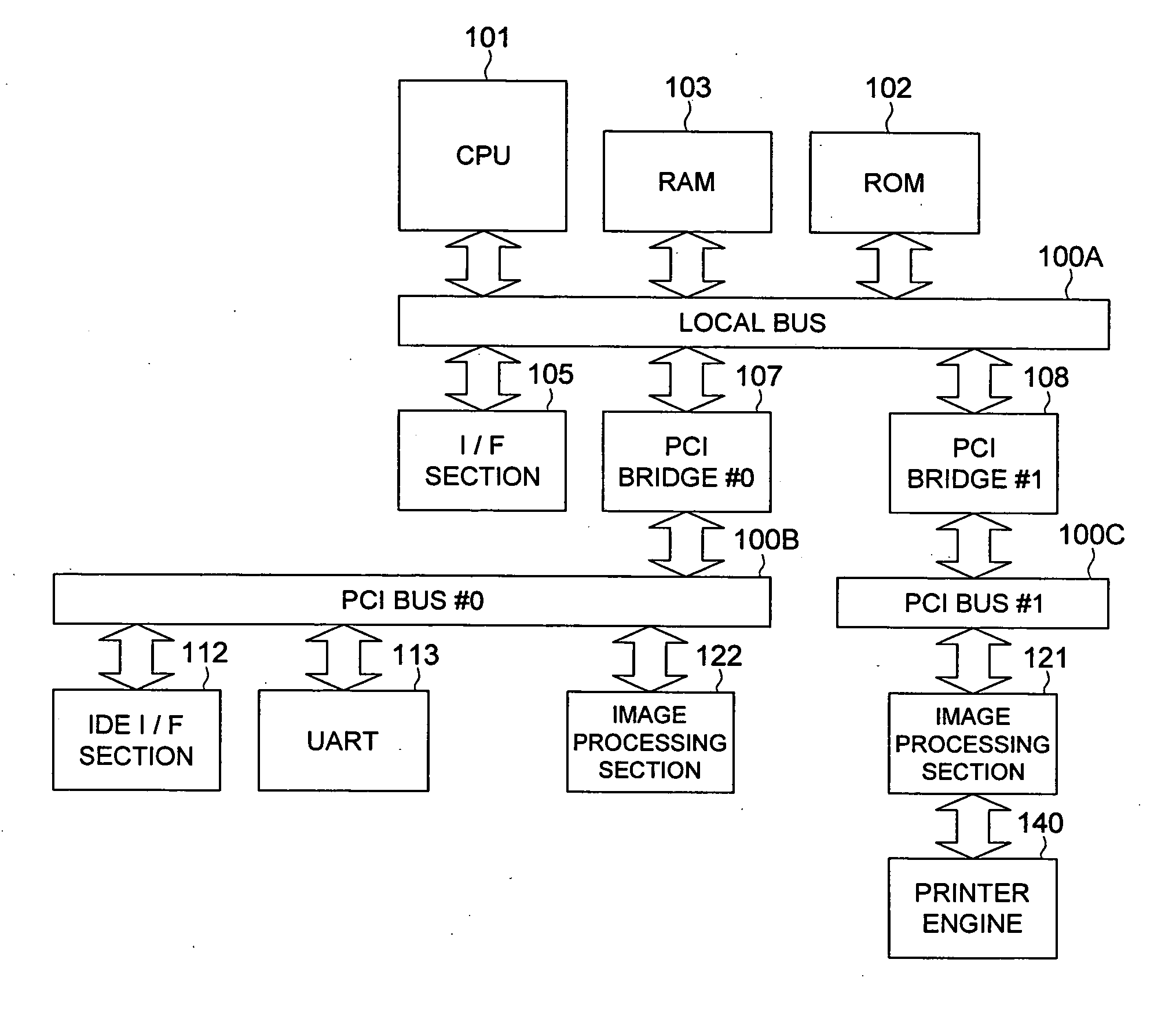
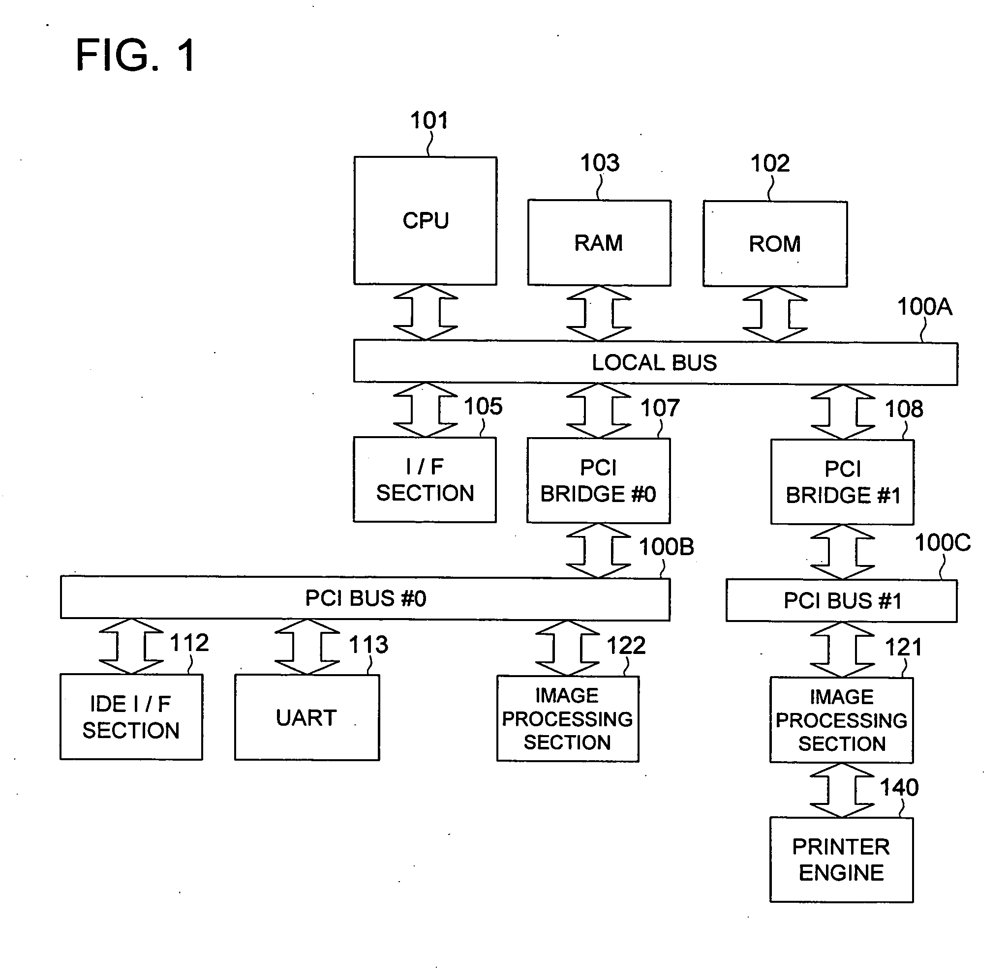
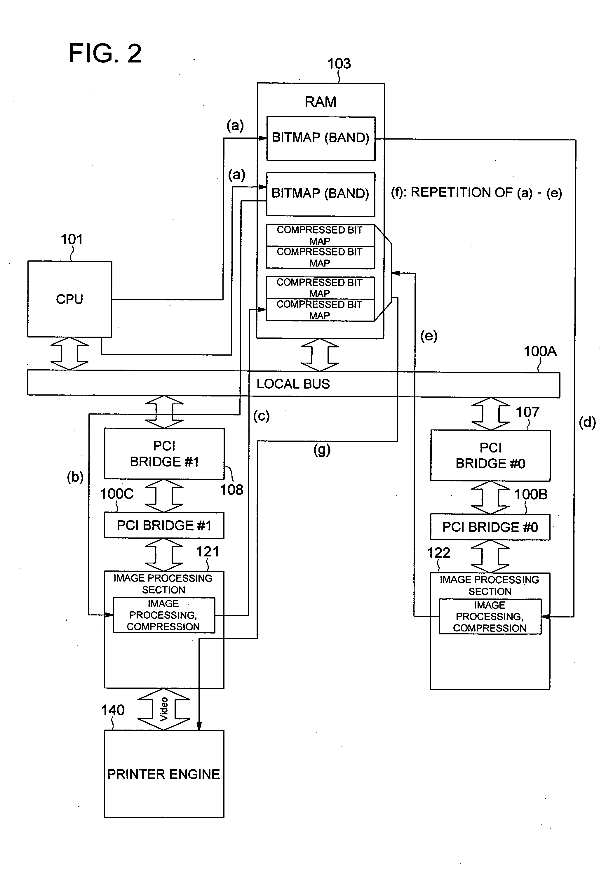
[0063]FIG. 1 illustrates a block diagram of the configuration of an image forming apparatus of the first embodiment of the present invention. In FIG. 1, a CPU 101 as a controller, a ROM 102 as memory for storing various setting data, a RAM 103 as memory (image memory) capable of being rewritten for memorizing image data, and an I / F section being a UART for communicating with the outside of the image forming apparatus and a LAN interface are connected with a local bus 100A which uses an external bus of the CPU 101 as it is.

[0064] An IDE I / F section 112, a UART 113 for serial communication and an image processing section 122 for executing an image processing of image data as an image processing hardware #2 are connected with a PCI bus #0 (it will be called PCI bus 100B from now on) as a generic bus or an expanded bus, which is different from the local bus 100A described above. The PCI bus 100B is connected with the local bus 100A described above through a PCI brid...

second embodiment

The Second Embodiment

[0097]FIG. 7 illustrates a block diagram for showing the configuration of the image forming apparatus of the second embodiment of the present invention. In FIG. 7, duplicated descriptions will be eliminated by giving the same number to the same part used in the FIG. 1 in the first embodiment.

[0098] In the second embodiment illustrated in FIG. 7, the image processing section 121 as an image processing hardware #1 and the image processing section 122 as an image processing hardware #2 are connected each other through a dedicated bus 100D. The dedicated bus 100D is designed to have the same data transmission speed of PCI bus. In the second embodiment, the printer engine 140 is connected with the image processing section 122.

[0099] Namely, in the second embodiment, a plurality of independent generic buses 100B and 100C are independently connected with a plurality of image processing sections 121 and 122. The plurality of image processing sections 121 and 122 has f...

third embodiment

The Third Embodiment

[0125]FIG. 13 illustrates a block diagram for showing the configuration of the image forming apparatus of the third embodiment of the present invention. In FIG. 13 duplicated descriptions will be eliminated by allotting the same number to the same part used in the FIG. 1 in the first embodiment.

[0126] In the third embodiment illustrated in FIG. 13, the image processing section 121 as an image processing hardware #1 and the image processing section 122 as an image processing hardware #2 are connected each other through a dedicated bus 100D. The dedicated bus 100D is designed to have the same data transmission speed as PCI bus. In the third embodiment, the printer engine 140 is connected with the image processing section 121.

[0127] Namely, in the third embodiment, a plurality of independent generic buses 100B and 100C are independently connected with a plurality of image processing sections 121 and 122. The plurality of image processing sections 121 and 122 has f...


PUM


Abstract

Disclosed is an image processing apparatus including: a controller for generating expanded image data; a local bus connected with the controller; a plurality of generic buses which are independent from each other; a plurality of image processing sections, each of which is respectively connected to each of the plurality of generic buses, for executing image processing of the expanded image data to generate processed image data; a plurality of bridges, each of which connects the local bus with each of the plurality of independent generic buses; and a memory section for storing at least one of the expanded image data and the processed image data, wherein the plurality of image processing sections share execution of image processing of the expanded image data generated by the controller, and the memory section memorizes the processed image data.

Description

CROSS REFERENCE TO RELATED APPLICATION [0001] The present application is based on Japanese Patent Application No. 2006-020990 filed with Japan Patent Office on Jan. 30, 2006, the entire content of which is relied on to correct translation errors in the present application. BACKGROUND OF THE INVENTION [0002] 1. Field of the Invention [0003] The present invention relates to an image processing apparatus and an image forming apparatus. Particularly the present invention relates to the image processing apparatus or the image forming apparatus in which the image processing section is connected with generic bus. [0004] 2. Description of Related Art [0005] In the image processing apparatus and the image forming apparatus, various interface controls and relatively high-speed data transmission have been attained by proving high-speed local bus for a CPU and separately proving generic bus such as PCI bus. [0006]FIG. 17 illustrates a block diagram to show a configuration of a conventional imag...

Claims


Application Information

Patent Timeline
Patent Type & Authority Applications(United States)
IPC IPC(8): G06K9/60
CPCG06T5/20
Inventor IDEHARA, TAKENORI
Owner KONICA MINOLTA BUSINESS TECH INC
Learn More