Image processing apparatus
a technology for processing apparatus and image, applied in the direction of image memory management, electrical apparatus, hardware for processing images, etc., can solve the problems of increasing the necessary line memory capacity, large circuit scale, and increasing the amount of dram access data, so as to improve the image processing speed and suppress the access count
- Summary
- Abstract
- Description
- Claims
- Application Information
AI Technical Summary
Benefits of technology
Problems solved by technology
Method used
Image
Examples
first embodiment
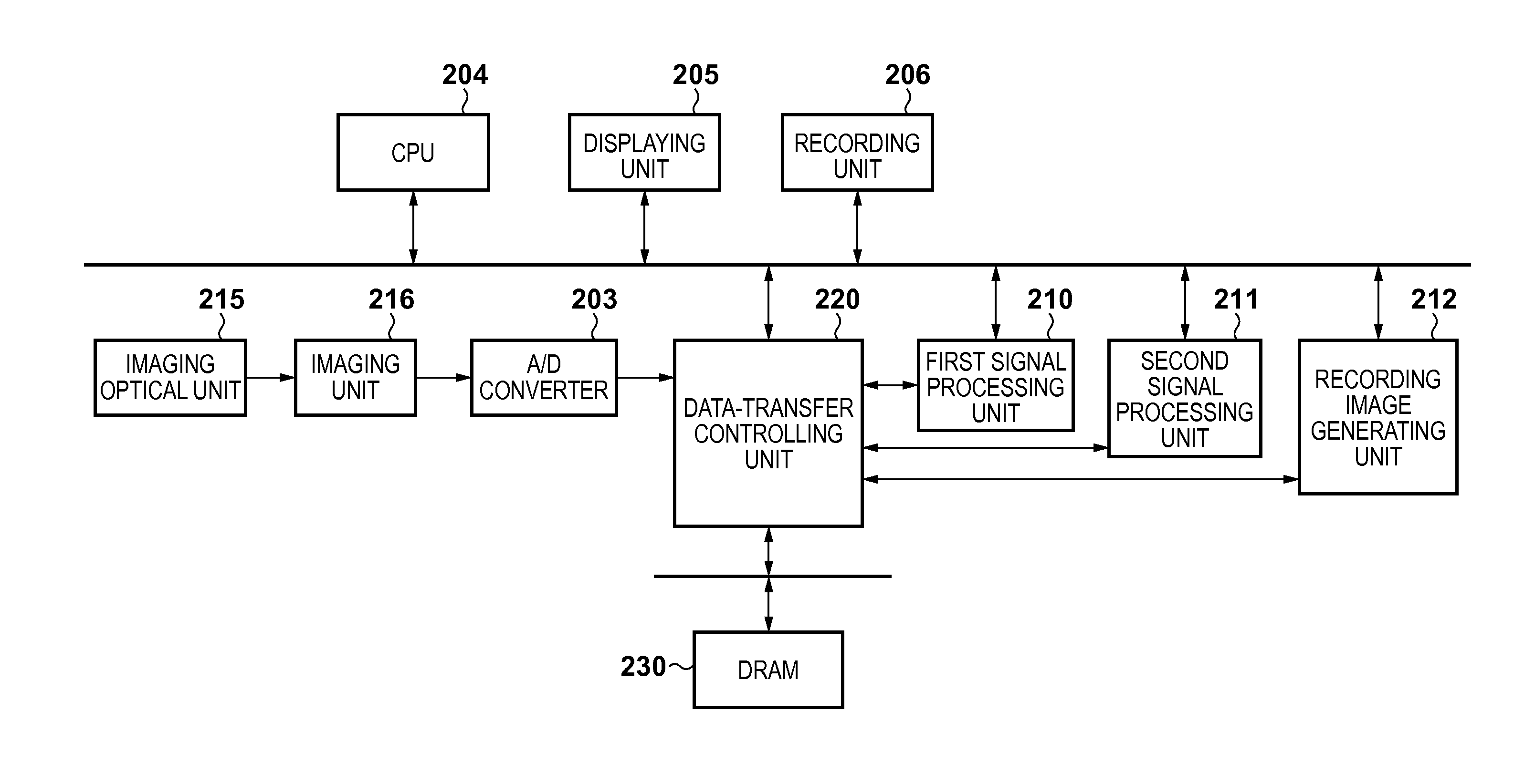
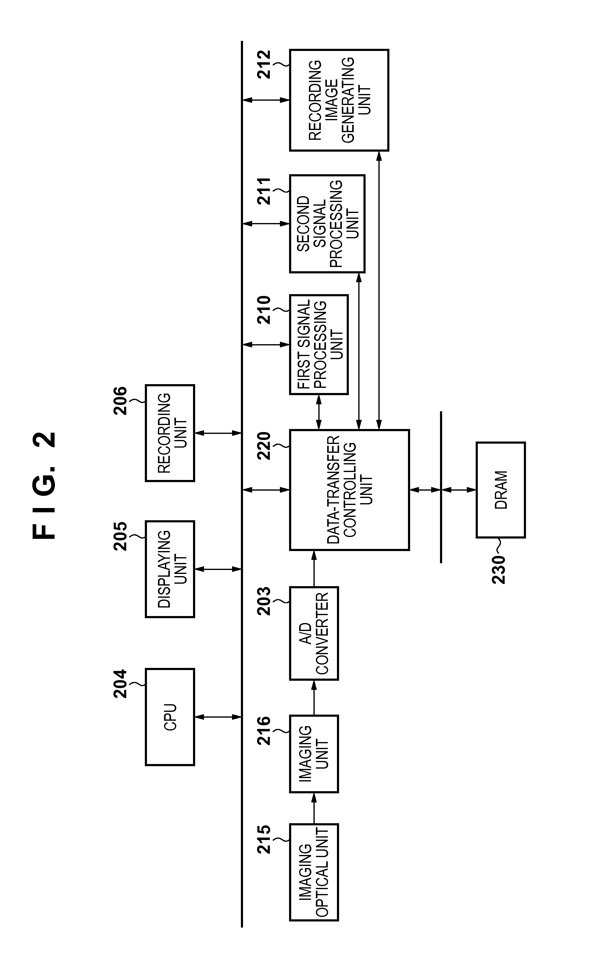
[0028]FIG. 2 is a block diagram showing the arrangement of an image processing apparatus according to the first embodiment. In the first embodiment, the image processing apparatus is applied to a digital camera.
[0029]Referring to FIG. 2, an imaging optical unit 215 is formed from a lens, a stop, and the like and adjusts focus and exposure. An imaging unit 216 such as a CCD converts an optical image into an electrical signal. An A / D converter 203 converts an analog image signal from the imaging unit 216 into digital image data. A DRAM 230 functions as a buffer memory to temporarily store data and also to do various kinds of processing. A data-transfer controlling unit 220 intervenes between a plurality of signal processing units and controls image data writing / reading in / from the DRAM 230. A CPU 204 performs various kinds of control via a bus. A first signal processing unit 210 and a second signal processing unit 211 perform various kinds of image processing (noise reduction, distort...
second embodiment
[0057]The second embodiment will be described below. The arrangement of an image processing apparatus according to the second embodiment, the arrangement of a data-transfer controlling unit 220, the arrangement of the address controller of each DMAC, and the processing order of partial images in the image processing apparatus are the same as in the first embodiment, and a description thereof will be omitted.
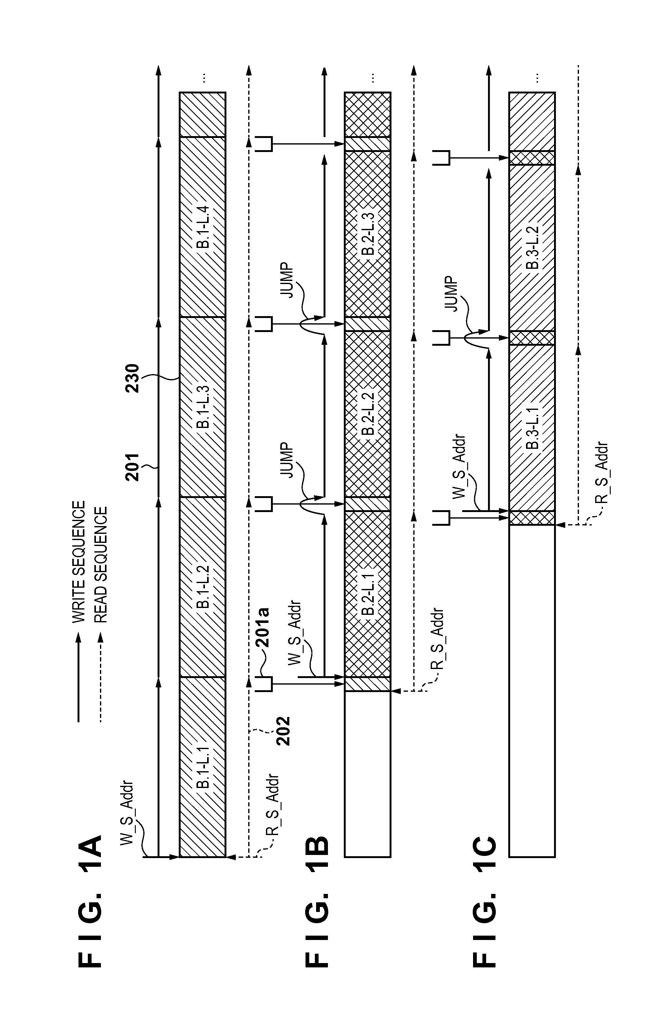
[0058]The second embodiment is different from the first embodiment in the size of the partial image to be processed by the image processing apparatus and the procedure of access from the image processing apparatus to the DRAM. In the second embodiment, access control to a DRAM 230 is performed so as to decrease the access data amount to the DRAM 230 and implement efficient access to the DRAM 230 even when the number of horizontal pixels of at least one of the plurality of partial images is different from that of the remaining partial images. More specifically, the positions of st...
third embodiment
[0070]The third embodiment will be described. The arrangement of an image processing apparatus according to the third embodiment, the arrangement of the address controller of each DMAC, the sizes of partial images to be processed by the image processing apparatus, and the processing order of partial images in the image processing apparatus are the same as in the second embodiment, and a description thereof will be omitted.
[0071]The third embodiment is different from the second embodiment in the arrangement of a data-transfer controlling unit 220, the DRAM access pattern of the image processing apparatus, and the DRAM access sequences of partial images. In the third embodiment, access to a DRAM 230 is controlled so as to suppress the count of short burst access to the DRAM 230 as compared to the second embodiment and implement efficient access to the DRAM 230 when the horizontal size difference between the partial images is equal to or smaller than a predetermined tolerance. In the t...
PUM
 Abstract
Description
Claims
Application Information
 - R&D
- Intellectual Property
- Life Sciences
- Materials
- Tech Scout
- Unparalleled Data Quality
- Higher Quality Content
- 60% Fewer Hallucinations
Browse by: Latest US Patents, China's latest patents, Technical Efficacy Thesaurus, Application Domain, Technology Topic, Popular Technical Reports.
© 2025 PatSnap. All rights reserved.Legal|Privacy policy|Modern Slavery Act Transparency Statement|Sitemap|About US| Contact US: help@patsnap.com


