Interchangeable bottletop aerator

a technology of aerators and bottle tops, applied in the direction of carburetor air, combustion air/fuel air treatment, separation processes, etc., can solve the problem of placing a limit on the velocity increase for decreasing orifice openings

Inactive Publication Date: 2014-05-01
KURU MURAT +1
View PDF2 Cites 6 Cited by
  • Summary
  • Abstract
  • Description
  • Claims
  • Application Information

AI Technical Summary

Benefits of technology

[0010]Decanting and aeration exposes wine to air, triggering oxidation and evaporation at the same time. The job of a good aerator is helping undesirable components to evaporate faster than fruit compounds oxidize in different wine selections. As the undesirable compounds dissipate, fruit seems to intensify giving the impression of softened structure. From a chemical standpoint, wine contains hundreds of compounds. However, the fruit character and thus allure of the wine come from a small portion of them. The fruit concentration and oxidation mitigating factors such as acidity, temperature, added sulfite concentration and naturally occurring sulfides create different responses to the aeration process. This necessitates the requirement of different aeration schemes for different wines.
[0013]The present invention comprises of a housing receptacle, which is removably engaged to a bottle and an aerator module, which is interchangeably inserted into said receptacle. The receptacle contains a single cylinder section extending into the bottle to seal the inside of the bottle opening. The inside of the cylinder is bifurcated to separate the outgoing liquid flow and incoming airflow to regulate the aeration process. The liquid channel has internal structures to speed and disturb the laminar flow thereby increasing the Reynolds Number (Re) and introducing turbulence in the flow field. The turbulent flow of the liquid enables faster and more homogeneous mixing of the air and the fluid, which happens to be essentially the aeration process. Conversely in a laminar flow field, the aeration can be limited to the layers adjacent to the flow regulating container boundaries resulting in heterogeneous and sub-optimal aeration. The turbulence of the flow field is characterized by the Re which is proportional to the density of the fluid, mean velocity of the relative movement of the fluid and the container, the hydraulic diameter of the flow channel and inversely proportional to the dynamic viscosity of the fluid. The density and the viscosity of the fluid cannot be changed for a given fluid and temperature for the practical purposes of our application. The speed with which the fluid flows is the function of gravitational forces acting on the fluid during the pouring process and is inversely proportional to the orifice opening area. Thus, in theory it is possible to increase the speed of the fluid flow by constricting the orifice size of the flow from the bottle. However, surface tension effects of the boundary layers place a limit in the velocity increase for decreasing orifice openings. The optimal orifice opening in this fluid channel depends on the fluid type and the acceptable time for a certain amount of fluid to pass through it and as such cannot be manipulated beyond certain ranges. Nevertheless, the Re can be further manipulated by introducing roughness in the boundary layers and including a stifling mechanism in the flow field. The fluid channel of the receptacle of the present invention includes a stirring post and the inside walls are textured for added roughness. These, in turn, force the fluid flow to be more turbulent while passing the liquid channel of the receptacle.
[0014]Thereafter, the liquid fluidly connects to the aerator module that is slidably inserted into the receptacle. The module can be a simple design of a venturi tube. It can have multiple sequential sections like described in some of the prior art. In the preferred embodiment of the invention, the interchangeable aerator module has a plurality of parallel channels to furcate the liquid flow. Each channel has non-uniformly placed aeration holes to create different flow patterns. These holes are located in different sections that are placed consecutively in series along the individual channels. An obturator chamber follows these sections to combine and thereby further mix the flow from the plurality of incoming parallel fluid channels. The distal wall of obturator chamber creates a wave breaking and fold-back effect on the incoming multiple flow fields. The opening in the obturator wall allows the desired amount of liquid to pass while regulating the turbulent flow back to laminar flow. This orifice has a dedicated aeration hole in the preferred embodiment. The following section of the module further regulates the flow to decrease spillage and spraying.
[0015]In the distal end of the receptacle, the preferred embodiment has an undisturbed cylindrical section to engage a plug cap to seal the assembly and so the liquid inside the bottle. The same cap is designed to be employed as a base cradle when the assembly is not placed on the bottle. The opening in this distal end of the receptacle is designed in a classical pouring rim shape to eliminate dripping.

Problems solved by technology

However, surface tension effects of the boundary layers place a limit in the velocity increase for decreasing orifice openings.

Method used


Image

  • Interchangeable bottletop aerator
  • Interchangeable bottletop aerator
  • Interchangeable bottletop aerator

Examples


Embodiment Construction

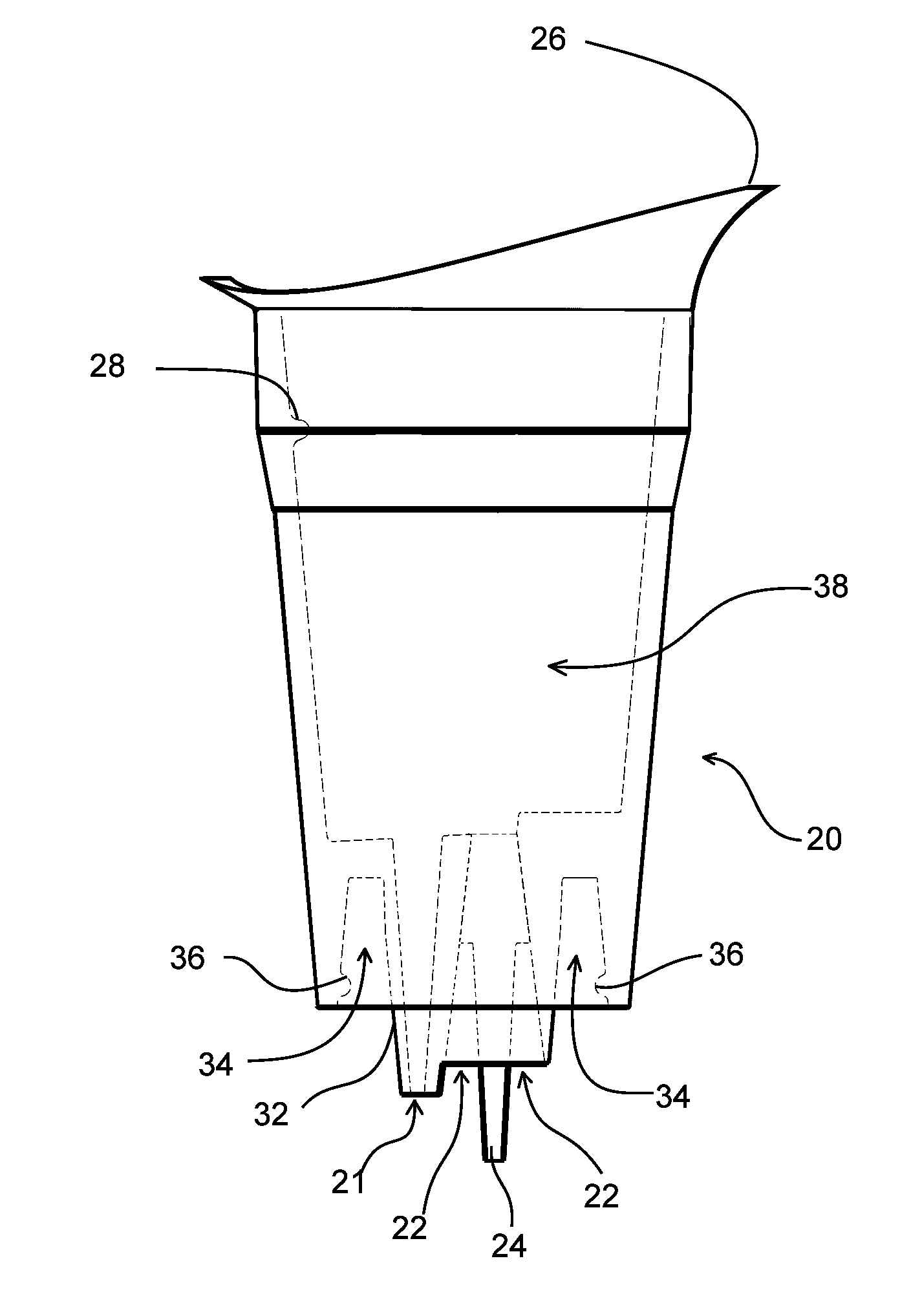
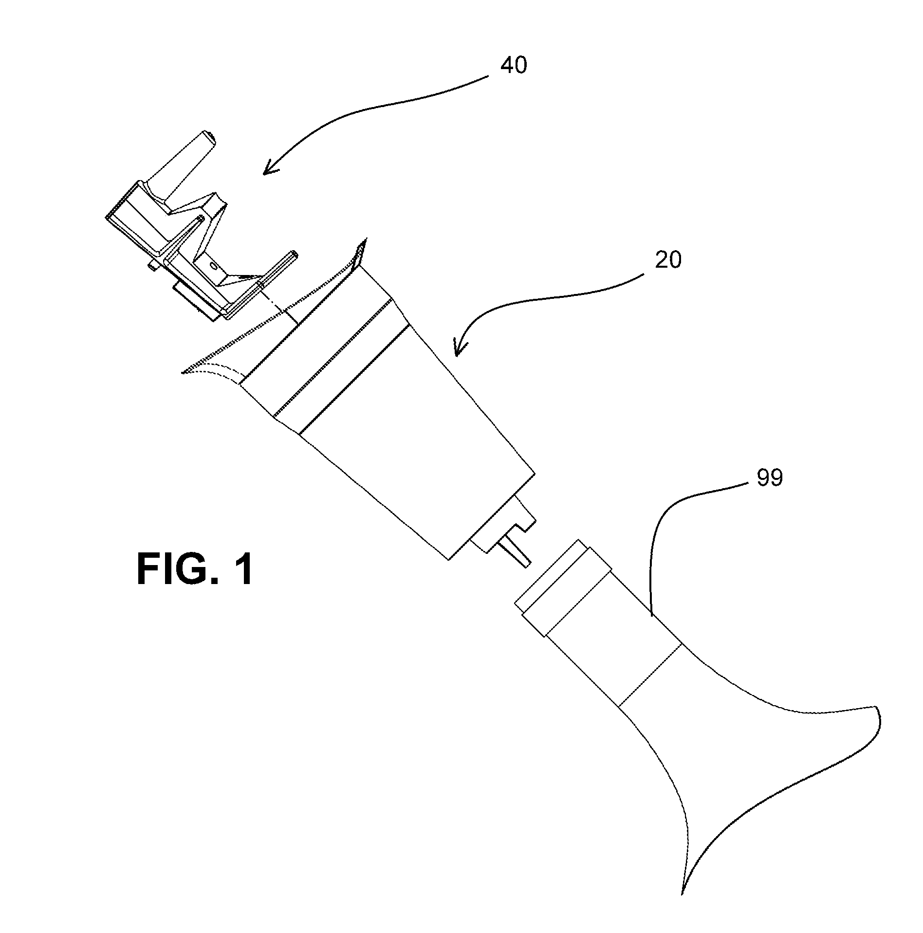
[0030]As illustrated in FIG. 1 the interchangeable bottletop aerator of the present invention consists of a receptacle, housing, carrier 20 and an interchangeable, replaceable aerator module, cartridge, insert 40 that is slidably inserted into receptacle 20, which is removably engaged to a bottle, container 99.

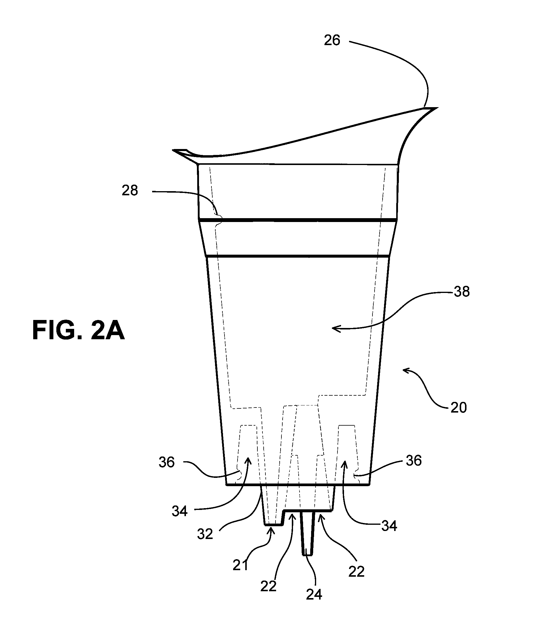
[0031]Receptacle 20 has a multi-lumen cylinder, cylindrical appendage member 32 at its proximal end to slidably engage into the bottle as illustrated in FIG. 2A. The cylinder is conical in nature to create the sliding into the bottle and removably seal the fluid connection between receptacle 20 and bottle 99. In the preferred embodiment of the interchangeable bottletop aerator there are two lumens inside cylinder 32. A channel, passage, duct 21 creates a passageway for the air going into the bottle to replace the emptied liquid. A second channel, passage, duct 22 is the path the emptying liquid follows. Liquid channel 22 is wider at the proximal end of receptacle 20 and narrow...


PUM

PropertyMeasurementUnit
softaaaaaaaaaa
angleaaaaaaaaaa
flow speedaaaaaaaaaa

Abstract

An interchangeable bottletop aerator for controllably mixing air with a liquid contained in a bottle. The apparatus includes a receptacle and an interchangeable aerator module that is inserted into the receptacle. The receptacle engages and seals the bottle through a multi lumen cylinder that extends inside the narrow neck of the bottle. It has internal structures to adjust flow characteristics of the liquid and encapsulates the module. The module has multiple channels and sections to apply predetermined aeration and flow speed to the contained liquid. The inserted module can be replaced on demand with a different module to change the aeration parameters and adapt the aeration characteristics to various liquids. The interchangeable bottletop aerator presents a solution to the changing aeration requirements of different liquids like wine in a compact, easy to use, and easy to produce package by means of simply replacing and employing different modules inside the receptacle.

Description

CROSS-REFERENCE TO RELATED APPLICATIONS[0001]N / ASTATEMENT REGARDING FEDERALLY SPONSORED RESEARCH OR DEVELOPMENT[0002]N / AREFERENCE TO SEQUENCE LISTING, A TABLE, OR A COMPUTER PROGRAM LISTING COMPACT DISC APPENDIX[0003]N / ABACKGROUND OF THE INVENTION[0004]1. Field of the Invention[0005]This invention relates to an interchangeable bottletop aerator that is removably engaged on top of a bottle to aerate a liquid such as different types of wine contained in the bottle while the liquid is being poured from the bottle.[0006]2. Discussion of the Prior Art[0007]The use of wine aerators is known in the prior art. Decanting as a means of aeration is as old as wine making. The old way of decanting wine in a vessel results in long wait periods and heterogeneous aeration of wine. Presently, more active means of decanting are performed by a plurality of aerators as well as old decanting containers. There exist several different configurations of aerators that are used external to the bottle, sit on...

Claims


Application Information

Patent Timeline
Patent Type & Authority Applications(United States)
IPC IPC(8): B01F3/04C12G1/00
CPCB01F3/04B01F25/4321B01F35/56B01F2101/17
Inventor KURU, MURATFREYRE, CARLOS V.
Owner KURU MURAT
Why Eureka
Try Eureka