
Microdevice and method for joining fluids

Inactive Publication Date: 2009-02-05
FUJIFILM CORP
View PDF30 Cites 12 Cited by
  • Summary
  • Abstract
  • Description
  • Claims
  • Application Information

AI Technical Summary

Benefits of technology

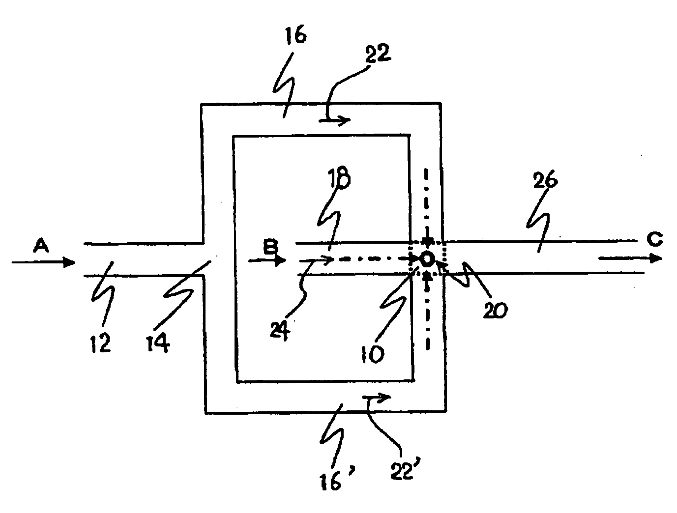
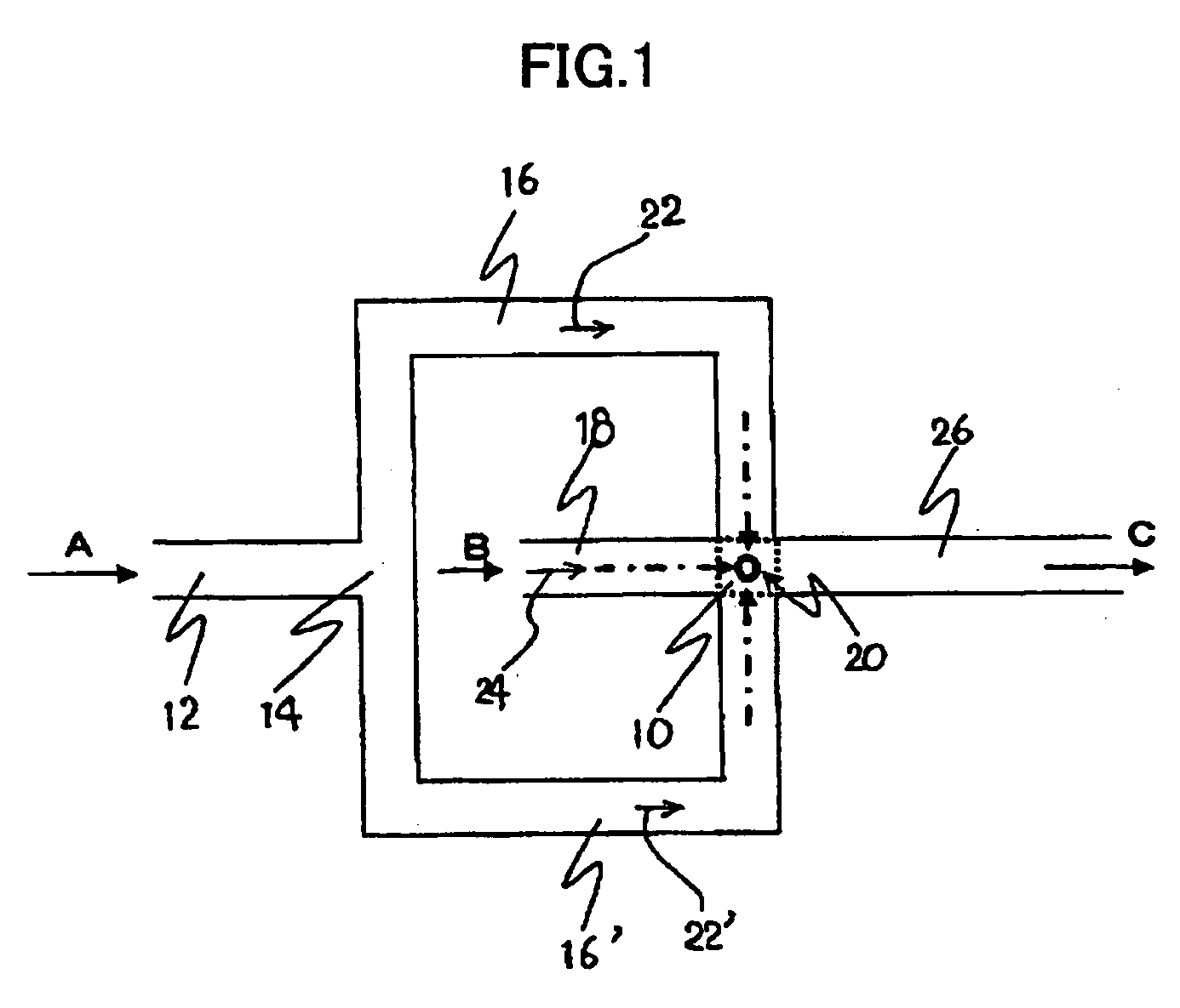
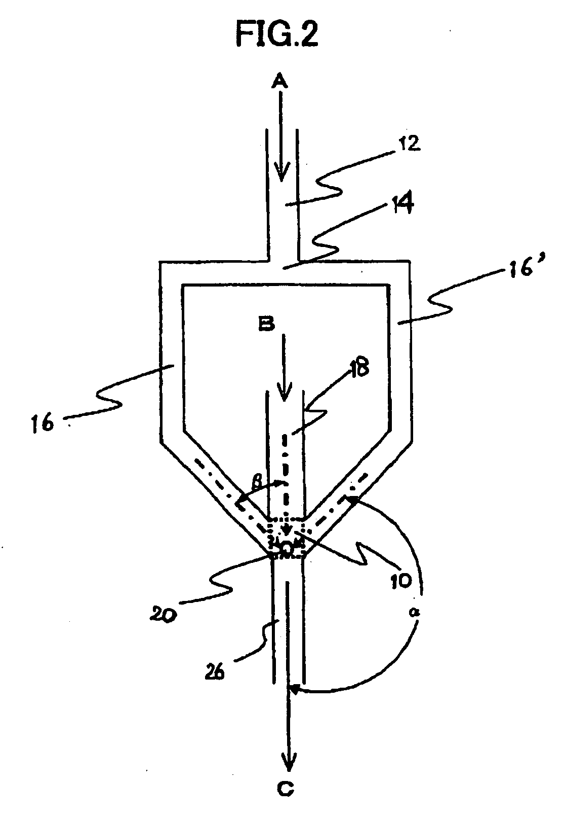
[0029]In the microdevice or the method for joining fluids of the present invention, when two or more kinds of different fluids are sent toward the joining region, at least one central axis of the supply channels (thereupon, streams) or the subchannels (thereupon, substreams) which supply each fluids of at least two or more kinds of fluids intersect each other at one point in the a joining region (with the proviso that at least one kind of the fluid is supplied toward the joining region through the subchannel (thereupon, in the form of the substream)).
[0030]In accordance with the microdevice or the method for joining fluids of the present invention, at least one object of the rapid and homogeneous mixing and the flexible responding to the operating condition of the mixing can be at least alleviated and preferably be canceled. As a result, the microdevice and the method for joining fluids are applicable to the mixing of two or more kinds of fluids and favorably suitable in executing a reaction together with the mixing.
[0031]In the present invention, because collisions and contacts occur in such a manner that the central axes of joining fluids intersect each other at one point, those fluids are instantly divided (or micronized) into small fluid wads by their kinetic energy, together with the contact condition of the fluid wads being improved. As a result, a contact interfacial area between the joining fluids suddenly increases and the mixing between those fluids will be accelerated, thereby achieving faster and more homogeneous mixing.

Problems solved by technology

However, the formed microchannel has a shallow depth relative to the width and as a result, the contact area of the fluids is not always sufficient.
Recently, a technology for forming a deeper microchannel by dry etching method is proposed, however, to form such a microchannel requires a large amount of expenses.
When making two kinds of reacting substances to be reacted by mixing with the use of such a microdevice, progression degree of reaction is different depending on the location of the microdevice, resultantly failing to execute any homogenous reaction.
Generally, the microdevices are designed in a tailor-made fashion so that an optimum operation is possible for a specific operating condition, however, when using such a microdevice with different operating condition, there are many cases that the microdevice cannot demonstrate its ability sufficiently.
In other words, operating condition ranges in using the conventional microdevices are limited.
In the case of the microdevice designed to supply two kinds of fluids with the same quantity of the flow, for example, and the operating condition becomes such that the ratio between their quantities of the flow is largely different, it is not easy to stably mix the fluids keeping the ratio between their quantities of the flow constant.
As a result, any desired product is not certainly expected.
Solid precipitates, precipitated solid coheres, and they occlude the microchannel, failing to execute the mixing operation stably and continuously.
As a matter of course, when the intended precipitation occurs in the case of carrying out crystallization reaction to generate fine particles, the occlusion particularly makes problem.
As a result, an aggregation of fine particles occurred at a position immediately behind a slit part forming thin layers of each liquid to be supplied, a clogging generated within 10 minutes after starting to supply the liquid and a continuation of the operation became difficult.
As a result, it takes too long time for the fluid to pass through the piping and the coupling to execute the next mixing or reaction just after the first mixing or reaction.
On the other hand, regarding with the fluid existing in the piping or in the coupling, because the mixing or reaction is in an intermediate stage, when the process is stopped, such a fluid cannot be treated as a final product and will cause losses.
Moreover, it becomes difficult to realize the compact plant being advantageous of employing the microdevice.

Method used


Image

  • Microdevice and method for joining fluids
  • Microdevice and method for joining fluids
  • Microdevice and method for joining fluids

Examples


Embodiment Construction

[0073]The microdevice of the present invention has a function of supplying two or more kinds of fluids flowed into itself independently toward a joining region respectively, and a function of discharging those fluids from the joining region. The term “independently” means that each fluid flowing into the microdevice pass through different passages until the fluid arrives at a joining region, and different kinds of fluids do not flow through the same passage, i.e., meaning “supplied separately”.

[0074]In the microdevice of the present invention, two kinds or more fluids are supplied via an entrance port into the microdevice, and they are supplied toward the joining region through the supply channel. The supply channel is not particularly specified so long as it is a passage that supplies the fluid supplied into the microdevice toward the joining region, and usually, it is a capillary tube member having a circular or a rectangular cross-section. A fluid that flows through such a supply...


PUM


Abstract

There is provided a microdevice which supplies two or more kinds of fluids flowed into itself independently toward a joining region respectively, and which discharges those fluids from the joining region. The microdevice is constituted by a supply channel which supplies each fluid flowed into the microdevice toward the joining region and a discharge channel which discharges the joined fluid from the joining region toward outside of the microdevice, in a manner that a supply channel which supplies at least one kind of the fluid has a plurality of subchannels which supply the fluid supplied into the microdevice toward the joining region, and those subchannels and supply channels are formed so that at least one central axis of the plurality of subchannels and at least one central axis of the supply channel which supplies at least one kind of fluid other than the kind that the subchannel supplies or of the subchannel intersect at one point.

Description

TECHNICAL FIELD[0001]The present invention relates to a microdevice for joining plural kinds of fluids and a method for joining fluids. More particularly, it relates to the microdevice and the method for joining fluids by which mixing and / or reaction of the fluids flowing together in this manner is carried out. The microdevice and the method for joining fluids of the present invention may be used in the case of manufacturing materials and products, for example, by mixing or reaction of fluids in the fields of chemical industry and pharmaceutical industry.[0002]Additionally in the present invention, the term “fluid” is used as including a liquid and a liquid mixture which can be treated as a liquid. Examples of such mixture include a liquid containing a solid and / or a gas, and may be a liquid mixture containing powder like minute solids (e.g., metallic fine particles) and / or minute air bubbles. Further, the liquid may contain another kind of liquid being not dissolved, and may be, fo...

Claims


Application Information

Patent Timeline
IPC IPC(8): B81B1/00B01F15/02
CPCB01F5/0256B01F13/0059B01J19/0093B01J2219/00783B01J2219/00788B01J2219/00804B01J2219/00891B01J2219/00831B01J2219/00833B01J2219/0086B01J2219/00867B01J2219/00873B01J2219/00889B01J2219/00822B01F25/23B01F33/30
Inventor MAE, KAZUHIROYOSHIDA, JUNICHISUGA, SEIJIKAWAGUCHI, TATSUYATANABE, JUNDAITO, NOBORUNAGASAWA, HIDEHARUNOMURA, HIDEYUKIHIKAGE, SHIGEKIYUBE, KUNIO
Owner FUJIFILM CORP
Learn More