
Vehicle horn control assembly

a technology for horn control and vehicles, applied in the direction of electric devices, acoustic signal devices, transportation and packaging, etc., can solve the problems of overly difficult accidental triggering of conventional horn control assemblies to sound the horn,

Inactive Publication Date: 2014-05-08
NISSAN MOTOR CO LTD
View PDF4 Cites 28 Cited by
  • Summary
  • Abstract
  • Description
  • Claims
  • Application Information

AI Technical Summary

Benefits of technology

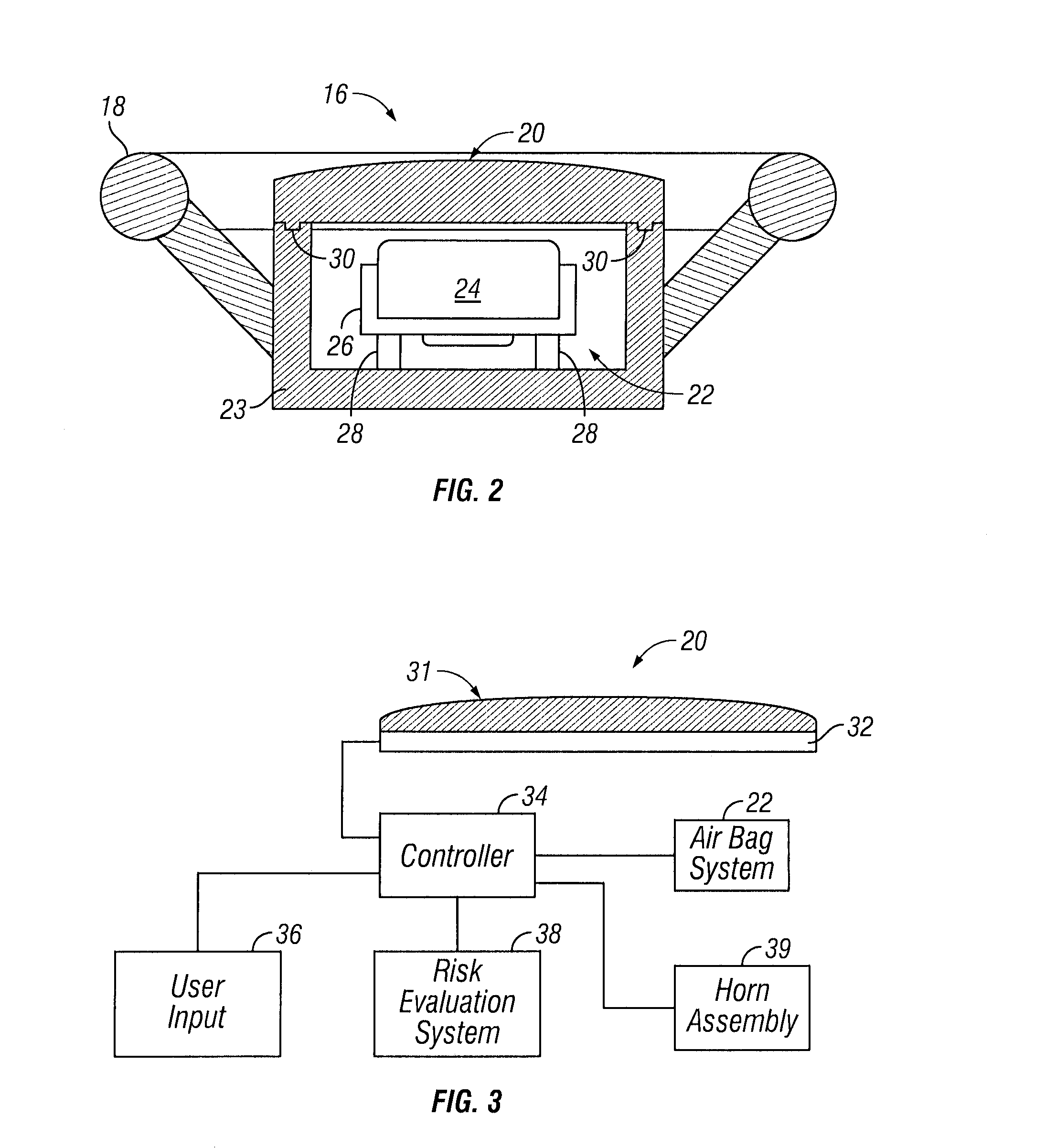
The present invention provides a vehicle horn control assembly consisting of a sensor assembly and a controller. The sensor assembly has multiple sensor zones that output pressure signals when a user touches them. The controller analyzes these signals over time to determine the way the user touches the assembly and activates the vehicle horn. This information is then used to set a pressure threshold for each sensor zone, above which the controller will activate the horn. The technical effect of this invention is to provide a more accurate and precise control for activating the vehicle horn, based on the unique touching characteristics of each individual user.

Problems solved by technology

However, conventional horn control assemblies may accidentally be triggered to sound the horn if the driver inadvertently depresses the horn control assembly during normal driving operations, when entering or leaving the vehicle, and so on.
Additionally, conventional horn control assemblies can become overly difficult to trigger in the event that underlying mounting structures such as springs become damaged or are inadvertently omitted from the assembly.

Method used


Image

  • Vehicle horn control assembly
  • Vehicle horn control assembly
  • Vehicle horn control assembly

Examples


Embodiment Construction

[0015]Selected embodiments will now be explained with reference to the drawings. It will be apparent to those skilled in the art from this disclosure that the following descriptions of the embodiments are provided for illustration only and not for the purpose of limiting the invention as defined by the appended claims and their equivalents.

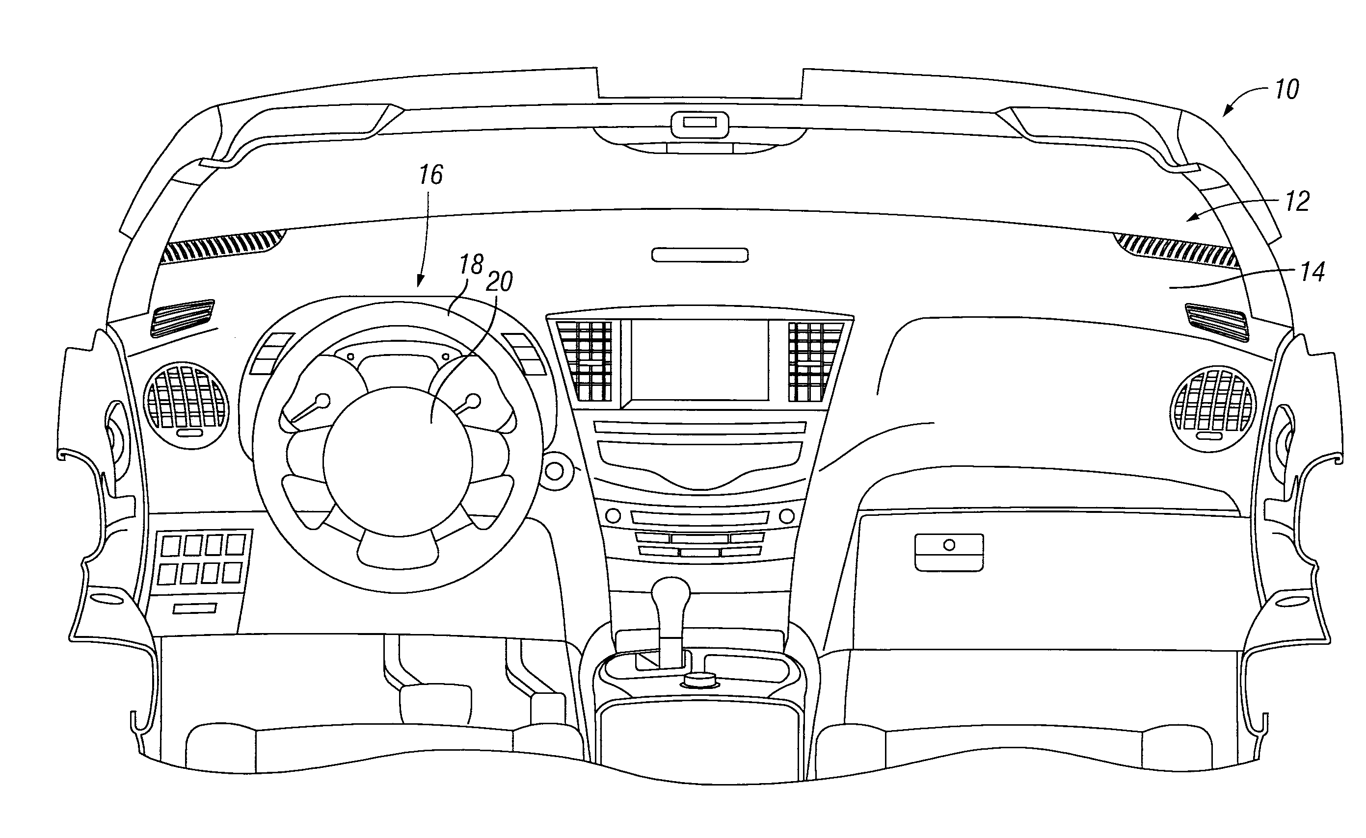
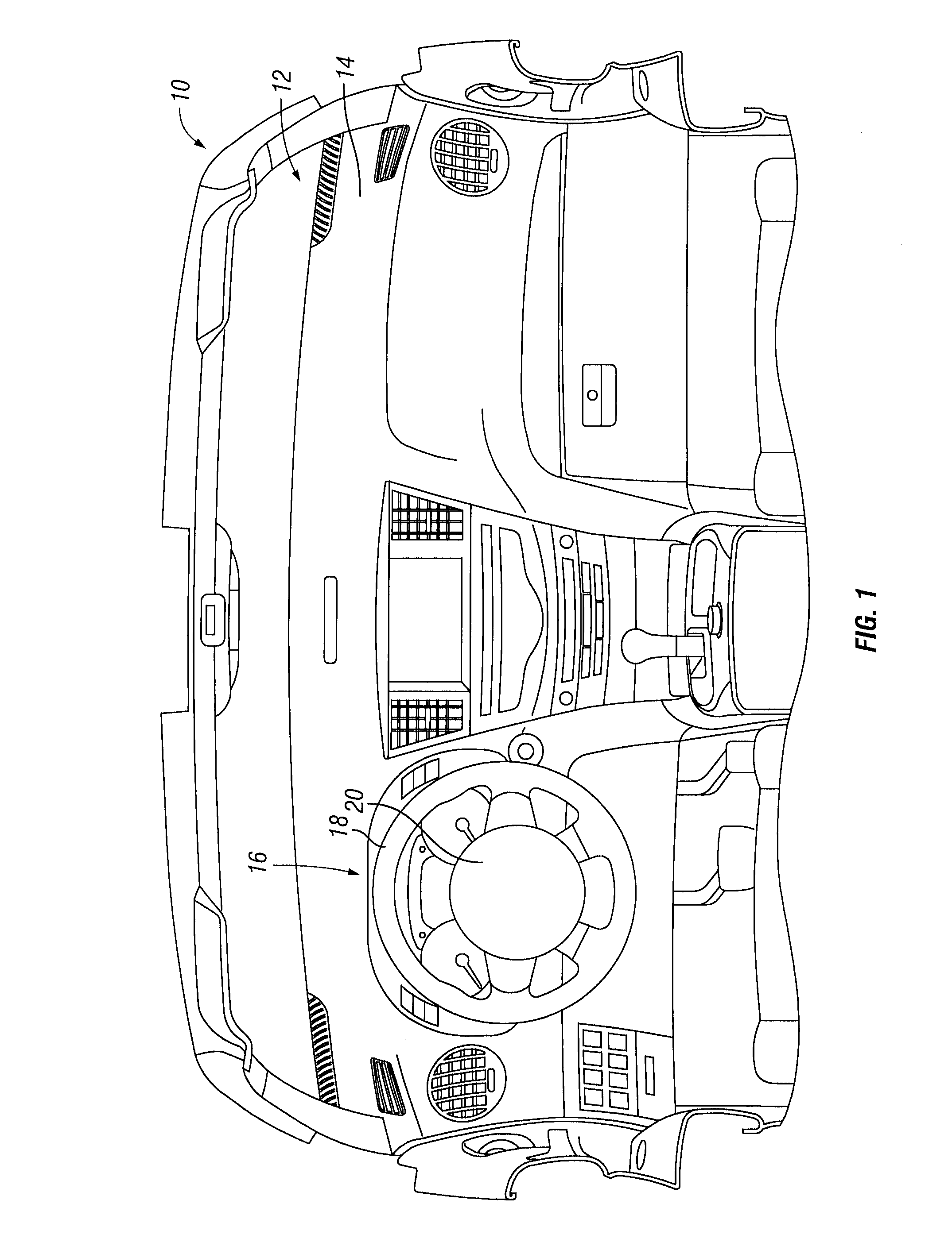
[0016]Referring initially to FIG. 1, a vehicle 10 such as an automobile, truck, van, SUV and so on includes a passenger compartment 12. A vehicle dash 14 is typically positioned toward the front of the passenger compartment 12. The vehicle 10 further includes a steering assembly 16 for controlling the steering direction of the vehicle 10. The steering assembly 16 includes a steering wheel 18 and a horn activation apparatus, which is referred to herein as a sensor assembly 20. Typically, the sensor assembly 20 is positioned at or near the center of the steering wheel 18 as part of a vehicle horn control assembly as discussed herein. However, the se...


PUM


Abstract

A vehicle horn control assembly comprises a sensor assembly and a controller. The sensor assembly has a sensor array that includes a plurality of sensor zones, with each of the sensor zones being configured to output a respective pressure signal in response to a respective amount of force applied thereto. The controller is configured to determine, based on the respective pressure signals output over a period of time, a touching characteristic representing a manner in which a user touches the sensor assembly to activate a vehicle horn. The controller is further configured to set a respective pressure threshold for each of the sensor zones above which the controller activates the vehicle horn based on the touching characteristic.

Description

BACKGROUND[0001]1. Field of the Invention[0002]The present invention generally relates to a vehicle horn control assembly. More specifically, the present invention relates to a vehicle horn control assembly having a plurality of horn operating tactile sensor zones that can be set to operate at different contact thresholds based on the touching characteristics of individual users.[0003]2. Background Information[0004]Vehicles such as automobiles, trucks, SUVs and so on are equipped with a horn or other type of warning system. A horn control assembly for activating the horn is mounted in the steering wheel, and is typically at a central location on the steering wheel. The horn control assembly is activated by sensed contact between two or more solid components that is generated when a driver applies sufficient force to the steering wheel. Therefore, the driver can easily activate the horn by applying pressure to the horn control assembly while maintaining their hands on the steering wh...

Claims


Application Information

Patent Timeline
IPC IPC(8): B60Q5/00
CPCB60Q5/003
Inventor VERNER, SARAH
Owner NISSAN MOTOR CO LTD
Learn More