
Bicycle Cuff

a bicycle and cuff technology, applied in the direction of garment suspenders, gaiters, pats, etc., can solve the problems of grease and dirt damaging the lower portion of the right pant leg, dangerous accidents, and damage to the clothing and health of people riding bicycles, so as to and improve the safety of riding

Inactive Publication Date: 2014-05-15
STARK JENIFER +1
View PDF4 Cites 5 Cited by
  • Summary
  • Abstract
  • Description
  • Claims
  • Application Information

AI Technical Summary

Benefits of technology

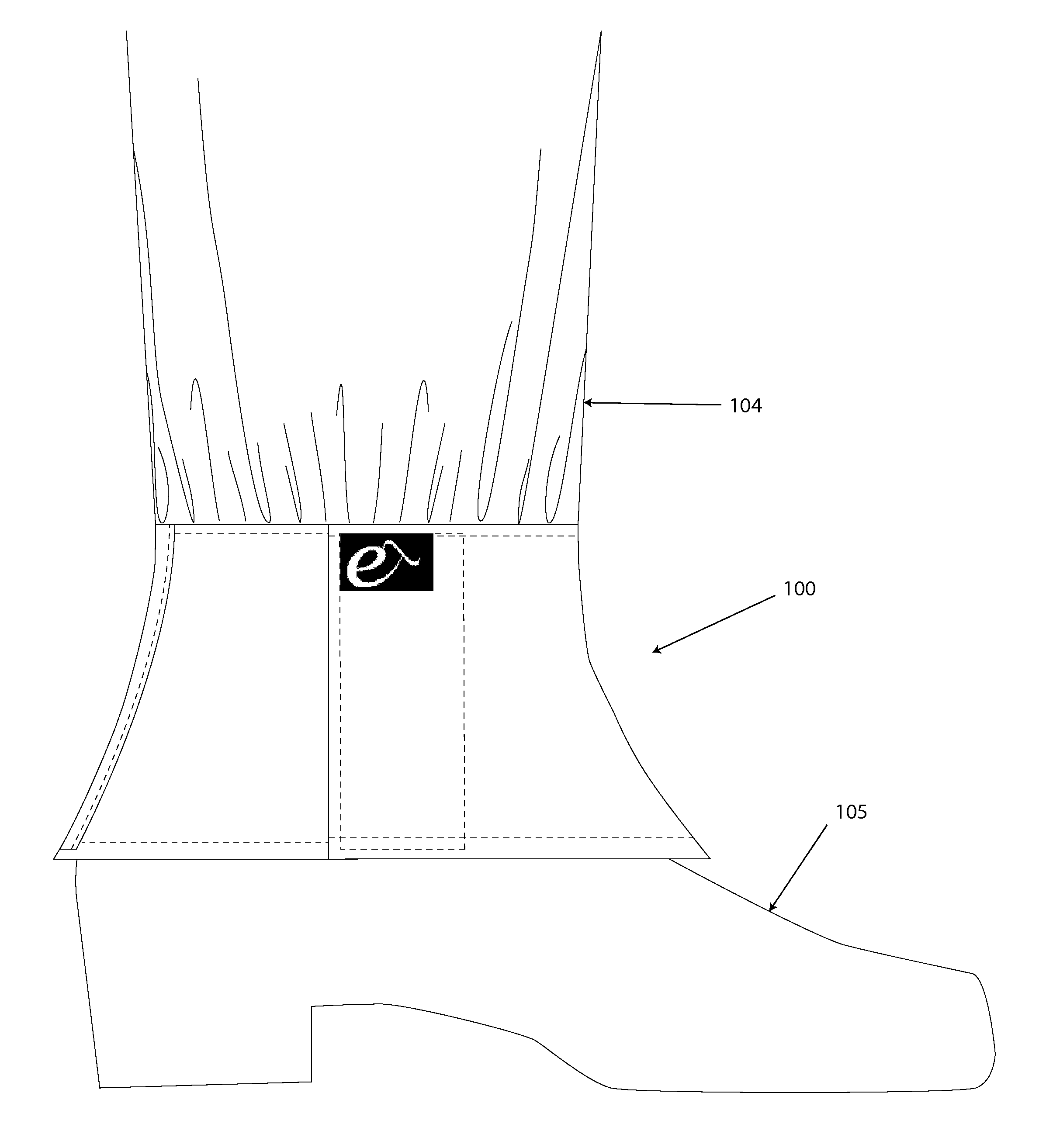
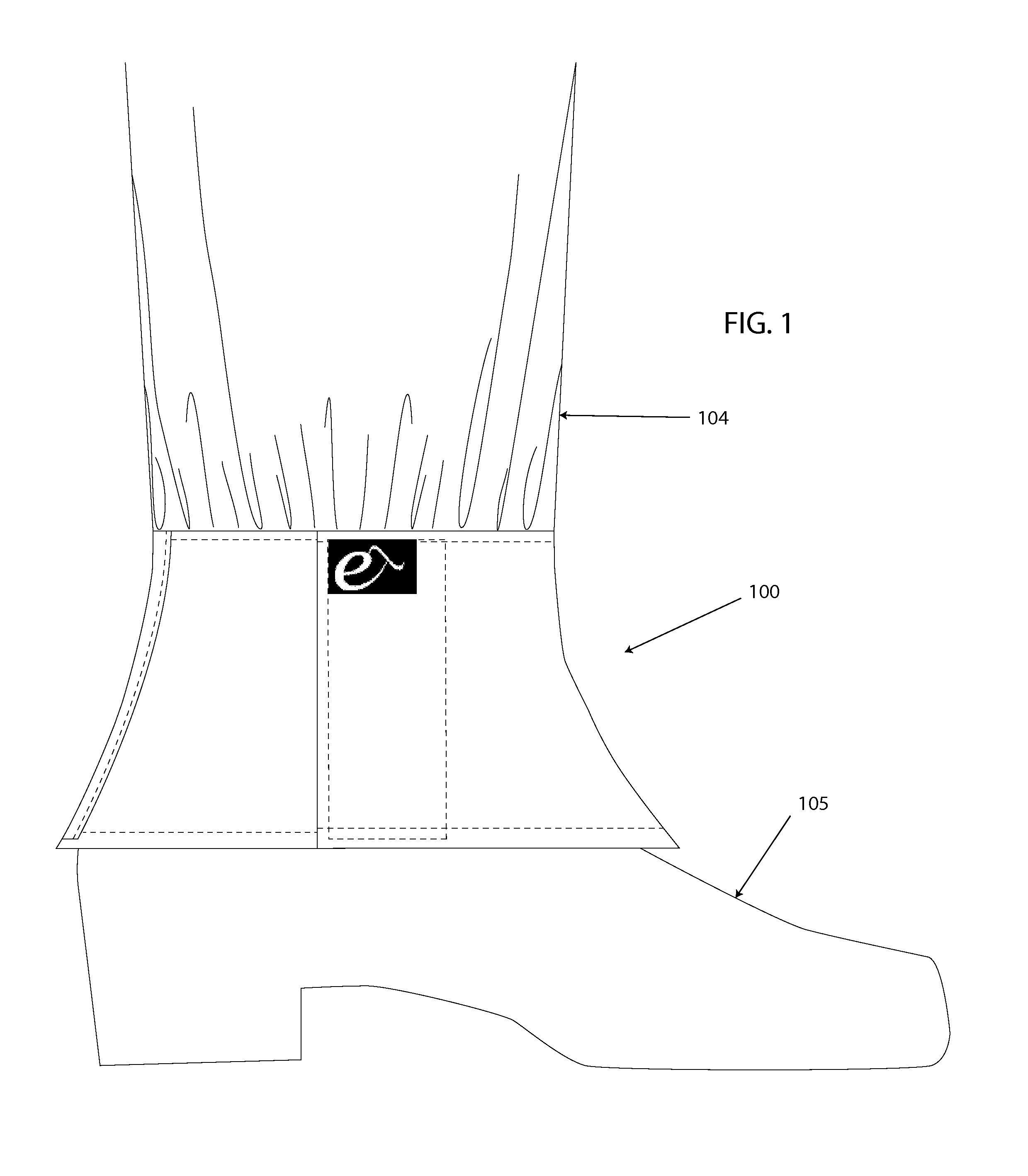
The patent describes a protective cuff for bicycle riders that is designed to cover the rider's legs, pants, shoes, and shoelaces. The cuff is made from a flexible fabric that is shaped like a triangles and is designed to fit snugly around the rider's ankle and shoe. The cuff is secured with a coupler and can be easily adjusted to fit different sizes of ankle and shoe. The technical effect of this invention is to provide a comfortable and protective ride for bicycle riders by keeping loose material away from bicycle chains and front gears, which can potentially cause accidents. The protective cuff can be easily put on and removed, and can be easily rolled, folded, and carried by the cyclist when not riding.

Problems solved by technology

People riding bicycles are often exposed to damage to their clothing and their health from the condition of their bicycle chain and front gear(s), and their proximity to loose articles of clothing near the feet and ankles.
As a result, the material of the rider's pants frequently comes into contact with the bicycle chain and front gear(s), causing grease and dirt to damage the lower portion of the right pant leg.
Damage also occurs when the right shoelace sometimes becomes caught between the chain and front gear(s), resulting in potentially dangerous accidents when the bicycle suddenly stops due to the caught shoelace.
A rider's shoes may also accumulate dirt and grease from proximity to the bicycle chain, causing damage to potentially expensive footwear.
However this is not a workable solution for the many riders who use bicycles as their primary mode of transportation, especially to and from work.
They have come largely in the form of strips, sometimes reflective, which band around the ankle but leave the hem of the pants to spread out and still potentially come into contact with dirt, grease, chains, and gears.
These strip-style ankle wraps come in a variety of materials and thicknesses, none of which provide any protection for the full bottom of the pant leg, or the shoe and shoelaces of the rider.
There have also been metal clips to again attempt to minimize the distance between the rider's pant leg and bicycle chain, but these too suffer from the same short comings as just noted for the strip-style ankle wraps, as well as having the additional failure of often popping right off of the rider's pant if not secured appropriately, or if strained by motion of the pant on the leg while riding.
The aforementioned options also do not provide any form of fashionable camouflage for the rider, as they often stand out in stark contrast to what the rider is wearing.
When riding in clothing that is not specifically designed for cycling, this is often a negative as the rider wishes to travel as seamlessly on a bicycle as he or she might by foot, subway, bus, or car.
Any accessory that is seen to make the rider less stylish or more encumbered is often skipped in favor of alternatives that inevitably result in damage to the rider's skin and clothing, such as rolling up the right pant leg (which often results in grease on the leg itself and interior of the right pant leg) or stuffing the right pant hem inside the rider's sock (which is often unsightly and usually results in grease and dirt on the rider's sock).
Other leg protection devices (e.g., gaiters and leggings) interfere with the pedaling motion by restricting ankle motion and interfering with the bicycle rider's shoe.

Method used


Image

  • Bicycle Cuff
  • Bicycle Cuff
  • Bicycle Cuff

Examples


Embodiment Construction

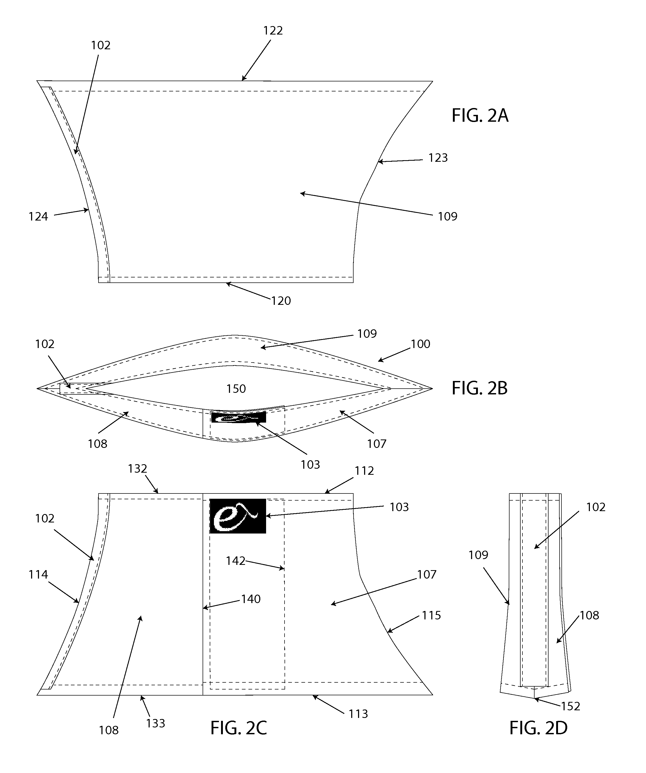
[0016]One embodiment of the cuff disclosed herein includes a woven nylon material coated on one side with urethane for water-resistance (referred to as water resistant urethane-coated nylon), loop and hook style closure on one side, reflective material at the center back vertical seam, and a brand logo label at the top left hand corner of the opening flap, on the outside of the cuff. The shape of the cuff approximately follows the curve of the rider's foot from ankle to the edge of the instep at the center front, and from ankle to the top of the heel at the center back. The loop and hook style fastener lies approximately halfway between the center front and center back of the foot, on the outside of the right leg. The cuff material runs from just above the ankle to just below the start of the heel of the foot (at the back center seam) and just beyond the start of the foot's instep (at the front center seam). The cuff is shaped to allow it to fall at these points on the ankle and the...


PUM


Abstract

A lightweight and portable bicycle cuff is disclosed to protect the lower leg, pants, and shoe of a bicycle rider from the effects of dirt, grease, and an exposed chain and front gear(s) while having minimal impact on pedaling by the bicycle rider. In certain embodiments the bicycle cuff provides increased visibility to traffic while riding. In some embodiments the cuff includes a flexible, water resistant woven material which conforms generally to the rider's ankle and foot by means of tailored shaping of the woven material, a strip of reflective material along the rear ankle area, and a loop and hook style closure on one side. In these embodiments the cuff covers from just above the ankle to approximately one third of the way down the front of the rider's shoe and just over the edge of the back of the rider's shoe.

Description

PRIORITY TO EARLIER FILED PROVISIONAL PATENT APPLICATION[0001]This application claims the benefit of the filing date of earlier filed co-pending U.S. Provisional Patent Application having Ser. No. 61 / 725,261 entitled “BICYCLE CUFF,” filed Nov. 12, 2012 and that shares co-inventorship with the present application. The entire teachings and contents of this Provisional Patent Application are hereby incorporated by reference herein in its entirety.FIELD OF THE INVENTION[0002]The present invention relates to lightweight and portable bicycle riding gear, clothing, and accessories, in particular to bicycle cuffs protecting the lower leg, pants, and shoes of bicycle riders from the effects of dirt, grease, and an exposed chain and front gear(s).BACKGROUND[0003]People riding bicycles are often exposed to damage to their clothing and their health from the condition of their bicycle chain and front gear(s), and their proximity to loose articles of clothing near the feet and ankles. While ridin...

Claims


Application Information

Patent Timeline
Patent Type & Authority Applications(United States)
IPC IPC(8): A41D27/10
CPCA41D27/10A41D17/00A41F17/02
Inventor STARK, JENIFERSTARK, JONATHAN
Owner STARK JENIFER
Learn More