
Contactless chip card with metal core

a chip card and metal core technology, applied in the field of contactless chip cards with metal cores, can solve the problems of affecting the contactless communication performance of known cards, affecting the operation of contactless modes on one face and the other face, and introducing metal plates into chip cards with detrimental effects on the electromagnetic level

Pending Publication Date: 2022-06-02
SMART PACKAGING SOLUTIONS SPS
View PDF3 Cites 0 Cited by
  • Summary
  • Abstract
  • Description
  • Claims
  • Application Information

AI Technical Summary

Benefits of technology

This patent describes a new design for a chip card that includes a metal plate embedded in the card body, with edges that are visible on the sides and over much of the thickness of the card. A through-hole is formed in the metal plate for the electronic module, and the metal plate is designed to have a maximized area and weight, and to contribute to the high-end look of the product. Preferably, the chip card has a single-piece metal edge formed from a single metal plate by forming at least one recess in the metal plate. This design gives the chip card a pleasing look from an esthetic point of view.

Problems solved by technology

However, as is known, introducing a metal plate into a chip card has detrimental consequences on the electromagnetic level, as the metal plate forms a partial or even substantial shield against the electromagnetic waves that may propagate between the contactless chip card and the chip card reader.
This has the possible consequence either of the contactless communication performance of known cards being impaired, or of the card operating only asymmetrically in contactless mode, that is to say that its operation in contactless mode is degraded on one face with respect to its operation on the other face.
However, this metal layer does not have a raised edge, so that the other layers of the card body that are also visible on the perimeter of the card are at risk of being delaminated.
This method is not suitable for obtaining hybrid contact and contactless chip cards, as there is no visible contact terminal block.
Furthermore, taking into account the electromagnetic shielding effect produced by the two metal plates, this method cannot be suitable for manufacturing contactless cards of radiofrequency performance compatible with the standards in force.

Method used


Image

  • Contactless chip card with metal core
  • Contactless chip card with metal core

Examples


Embodiment Construction

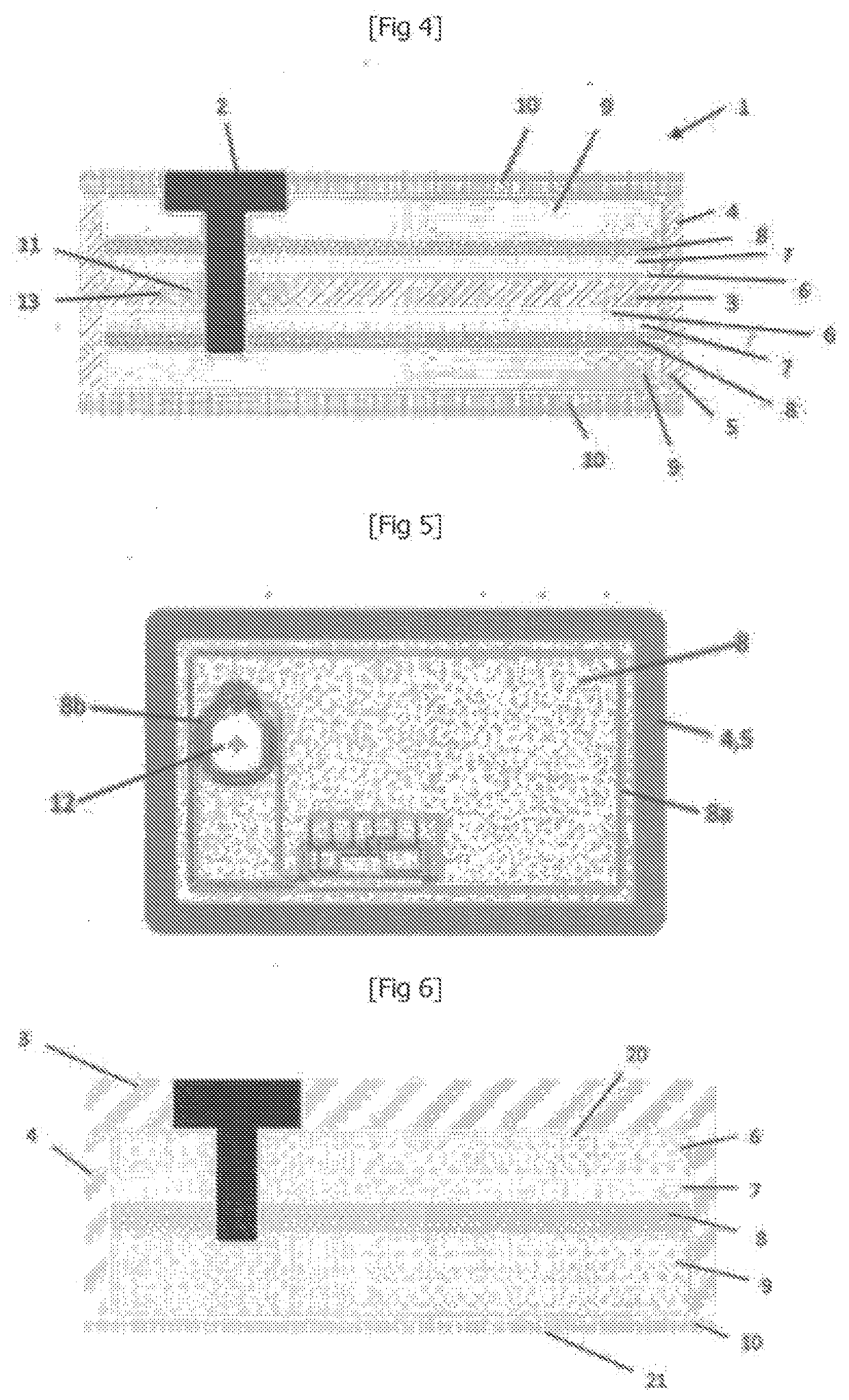
[0041]In order to make it easier to understand and see the structure, the thicknesses of the layers of materials in the cross-sectional views (FIGS. 4 and 6) are highly exaggerated with respect to the real proportions of a chip card.

[0042]Identical elements in FIGS. 4 to 6 bear the same reference numbers.

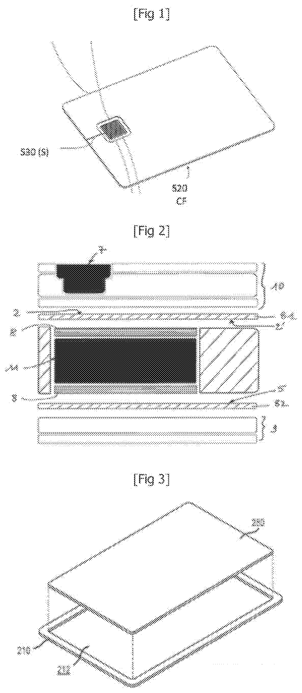
[0043]FIG. 1 corresponds to FIG. 5C of document US 2016 / 0110639 A1 (Finn), which describes in particular chip cards having a metal layer. According to this document, for correct contactless operation of this chip card the metal layer is required to have a slit (530 (S)). Now, this slit remains visible on the finished product in certain luminosity or lighting conditions, which is not acceptable to customers for high-end products, the appearance of which must be perfect,

[0044]FIG. 2 corresponds to FIG. 8 of document FR 3032094 A1 (Smart Packaging Solutions). It depicts a chip card comprising a metal plate 11 intended to make the card heavier, and two booster antennas on either side th...


PUM


Abstract

A contactless or hybrid contact and contactless chip card, includes a card body composed of a stack of layers and provided with a cavity into which an electronic module is inserted. The electronic module includes a microelectronic chip connected to an inductive or capacitive coupling means for coupling with, or a physical connection to, at least one antenna arranged in the card body. The card body comprises a metal plate forming a core and the periphery of which has at least one edge delimiting at least one recess in which the other layers of the chip card are positioned.

Description

[0001]The invention relates to contactless or hybrid contact and contactless identification cards, which are provided with a metal plate so as to strengthen the card or make it heavier.PRIOR ART[0002]The majority of known contactless chip cards or hybrid contact and contactless dual cards comprise a multilayer plastic card body, an electronic module inserted into a cavity of the card body and comprising a microelectronic chip, and an antenna arranged in the card body. The antenna of the card body is either electrically connected to output pads of the microelectronic chip or inductively coupled with the electronic module, which is itself provided with an antenna.[0003]Known chip cards have a standardized format according to ISO standard 7810, and they are in general made of plastic for reasons of cost and flexibility.[0004]Now, one developing segment of the market targets contactless chip cards, or contact and contactless dual chip cards, having physical characteristics that belong t...

Claims


Application Information

Patent Timeline
IPC IPC(8): G06K19/077G06K19/07
CPCG06K19/07745G06K19/07743G06K19/0723G06K19/07722
Inventor GERIN, GUILLAUMEDANLER-BAUMGARTNER, STEPHANRICHARD, DAMIEN
Owner SMART PACKAGING SOLUTIONS SPS
Learn More