Eureka AIR delivers breakthrough ideas for toughest innovation challenges, trusted by R&D personnel around the world.

Pressure measurement structure

Inactive Publication Date: 2014-05-15
IND TECH RES INST
View PDF6 Cites 35 Cited by
  • Summary
  • Abstract
  • Description
  • Claims
  • Application Information

AI Technical Summary

Benefits of technology

The patent text describes a pressure measurement structure that only requires one wiring layer, which results in a reduction in the number of screen boards, printing materials usage, and process time. The technical effect is improved efficiency and cost-effectiveness in the manufacturing process.

Problems solved by technology

Hence, given the limited measuring space, partial sensing area is certainly not functioned when wiring area and sensing area are in the same plane.
As a result, the accuracy of foot risk assessment project is decreased or the assessment may not be done in particular the assessment for center of pressure (COP).
Thereby, misjudgment for COP due to data vacancy of this part is likely to occur.
Consequently, how to improve the accuracy of pressure measurement device under the condition of limited measuring space is an important issue for the research personnel.

Method used


Image

  • Pressure measurement structure
  • Pressure measurement structure
  • Pressure measurement structure

Examples


Embodiment Construction

[0019]In the following detailed description, for purposes of explanation, numerous specific details are set forth in order to provide a thorough understanding of the disclosed embodiments. It will be apparent, however, that one or more embodiments may be practiced without these specific details. In other instances, well-known structures and devices are schematically shown in order to simplify the drawing.

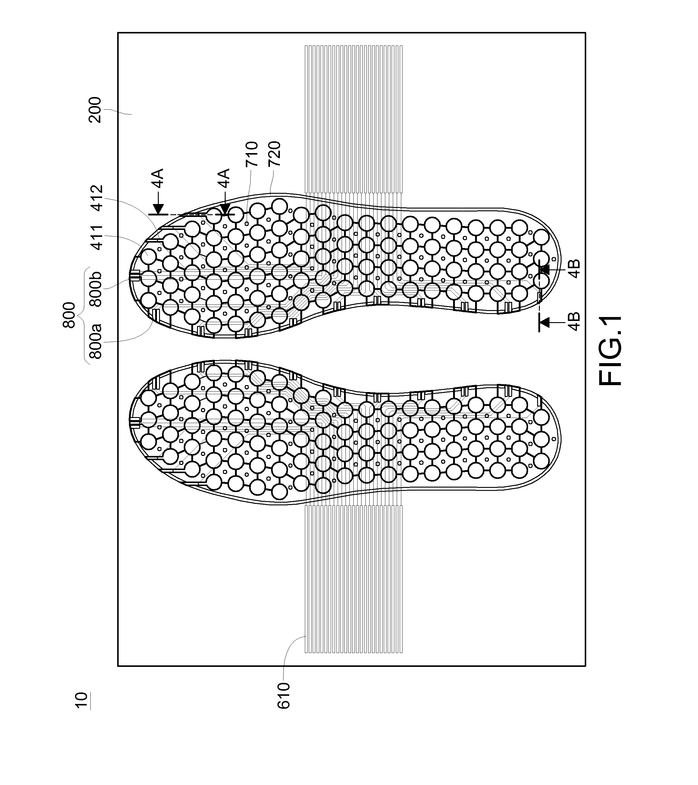
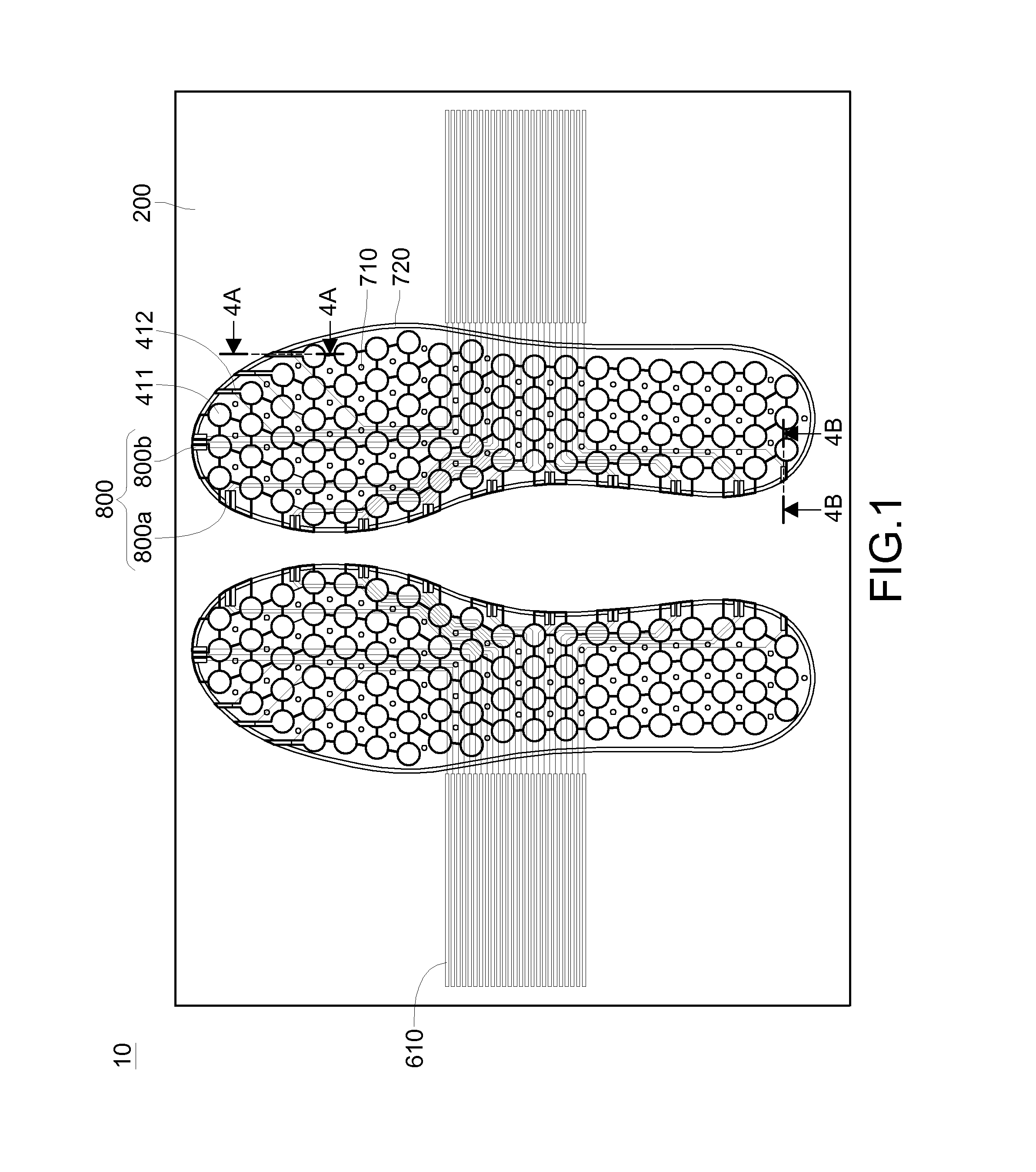
[0020]Please refer to FIG. 1. FIG. 1 is a schematic plan view of the pressure measurement structure according to an embodiment of the disclosure. In this embodiment, the pressure measurement structure 10 is configured for measuring the pressure of foot.

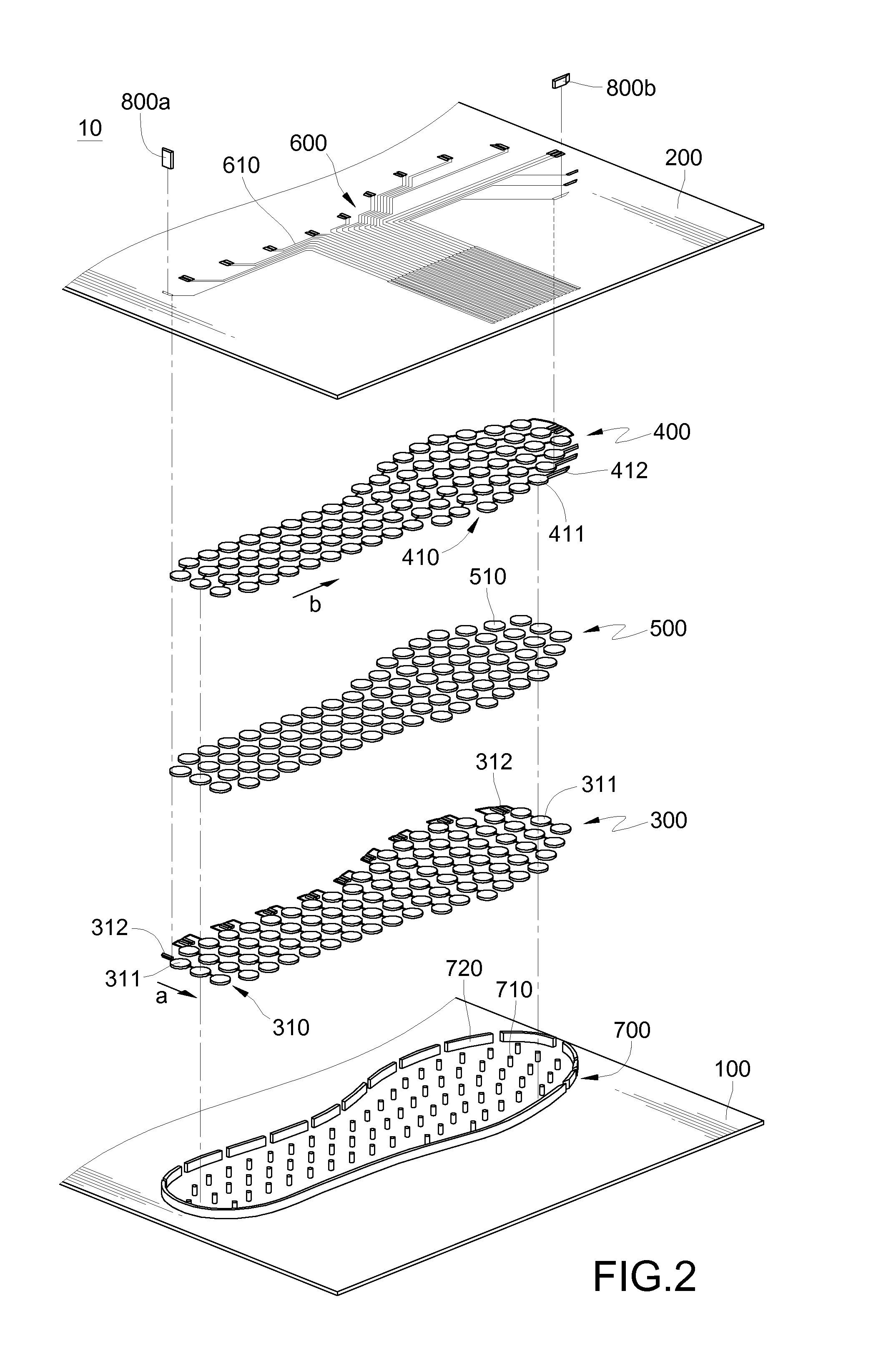
[0021]Please refer to FIG. 2, an exploded view of FIG. 1. The pressure measurement structure 10 of this embodiment comprises a first substrate 100, a second substrate 200, a first electrode layer 300, a second electrode layer 400, at least a piezoresistive layer 500 and a wiring layer 600. The pressure measurement structure 10 further...


PUM


Abstract

A pressure measurement structure includes a first substrate, a second substrate, a first electrode layer, a second electrode layer, at least a piezoresistive layer and a wiring layer. The second substrate faces towards the first substrate. The first electrode layer is disposed on the first substrate and faces towards the second substrate. The second electrode layer is disposed on the second substrate and faces towards the first electrode layer. At least a piezoresistive layer is located between the first electrode layer and the second electrode layer. A wiring layer is disposed on the second substrate and back to the first substrate. The wiring layer includes multiple wires. Part of the wires are electrically connected to the first electrode layer. The other part of the wires are electrically connected to the second electrode layer.

Description

CROSS-REFERENCE TO RELATED APPLICATIONS[0001]This non-provisional application claims priority under 35 U.S.C. §119(a) on Patent Application No(s). 101142301 filed in Taiwan, R.O.C. on Nov. 13, 2012, the entire contents of which are hereby incorporated by reference.TECHNICAL FIELD[0002]The disclosure relates to a pressure measurement structure, more particularly to a pressure measurement structure having a high density measuring array.RELATED ART[0003]Foot plays a very important role in supporting body weight, reducing stress for lower limbs and related joints, absorbing shock, relieving impact and controlling body balance when contacting the ground. These functions are realized by such tissues as the bones, ligaments and muscles that fit together.[0004]Among common people, at least 80% of them have foot problems Ankle and foot injuries will result in mechanics change to gait, to produce stress on other joints of lower limbs. Thereby, possibly joint lesions may occur. These problems,...

Claims


Application Information

Patent Timeline
IPC IPC(8): A61B5/103
CPCA61B5/1036A61B5/1038A61B2562/046A61B2562/166
Inventor CIOU, JYUN-KAILIN, YAN-RUNGLIOU, CHANG-HOCHEN, CHANG-YI
Owner IND TECH RES INST
Why Eureka
Eureka Blog
Learn More