
Reusable Distraction Device Simulator

a distraction device and simulator technology, applied in the field of reusable distraction device simulators, can solve the problems of reducing the effectiveness of training, reducing the cost of training, and exposing trainees using operational devices charged with a reduced training load to explosive hazards, etc., and achieves the effects of convenient, economical and safe us

Inactive Publication Date: 2014-05-15
CHONG CARLTON
View PDF1 Cites 8 Cited by
  • Summary
  • Abstract
  • Description
  • Claims
  • Application Information

AI Technical Summary

Benefits of technology

The present invention provides a reusable pneumatic distraction device that is convenient, economical, and safe to use. The device includes a housing with two gas reservoirs, a valve, a piston, and a delay mechanism. The valve is movable between a closed position and an open position to control the flow of gas. The piston is coupled to the valve and moves it towards its open position when there is a difference in gas pressure between the two reservoirs. A lock pin is releasably mounted to the valve to hold it in its closed position. The device also includes a porous plug to slow down the movement of the piston when the lock pin is released. The technical effects of the invention include improved safety, reliability, and efficiency of the pneumatic distraction device.

Problems solved by technology

While these prior operational distraction devices and training DDS are useful training tools, there are a number of draw backs associated with previous designs.
The lack of report reduces the effectiveness of training because trainees do not have an aural queue to initiate their actions.
Trainees using operational devices charged with a reduced training load are exposed to an explosive hazard as well pyrotechnic charges expose a training site to fire or blast damage.
Additionally, reduced training charges are expensive and are logistically difficult to handle and ship since they are considered to be hazardous material.

Method used


Image

  • Reusable Distraction Device Simulator
  • Reusable Distraction Device Simulator
  • Reusable Distraction Device Simulator

Examples


Embodiment Construction

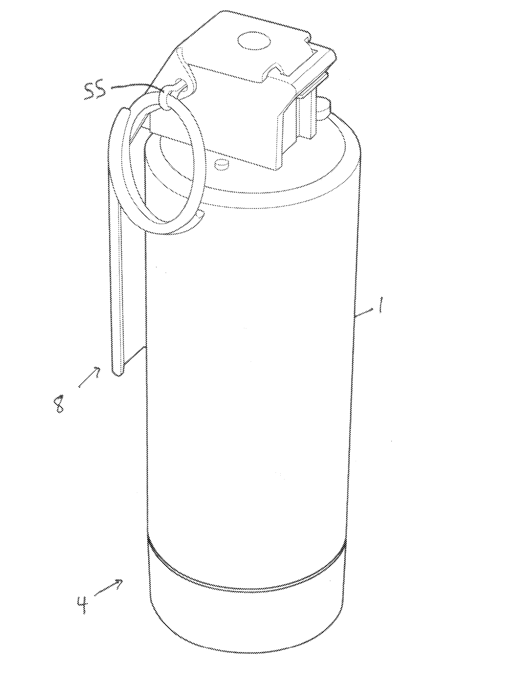
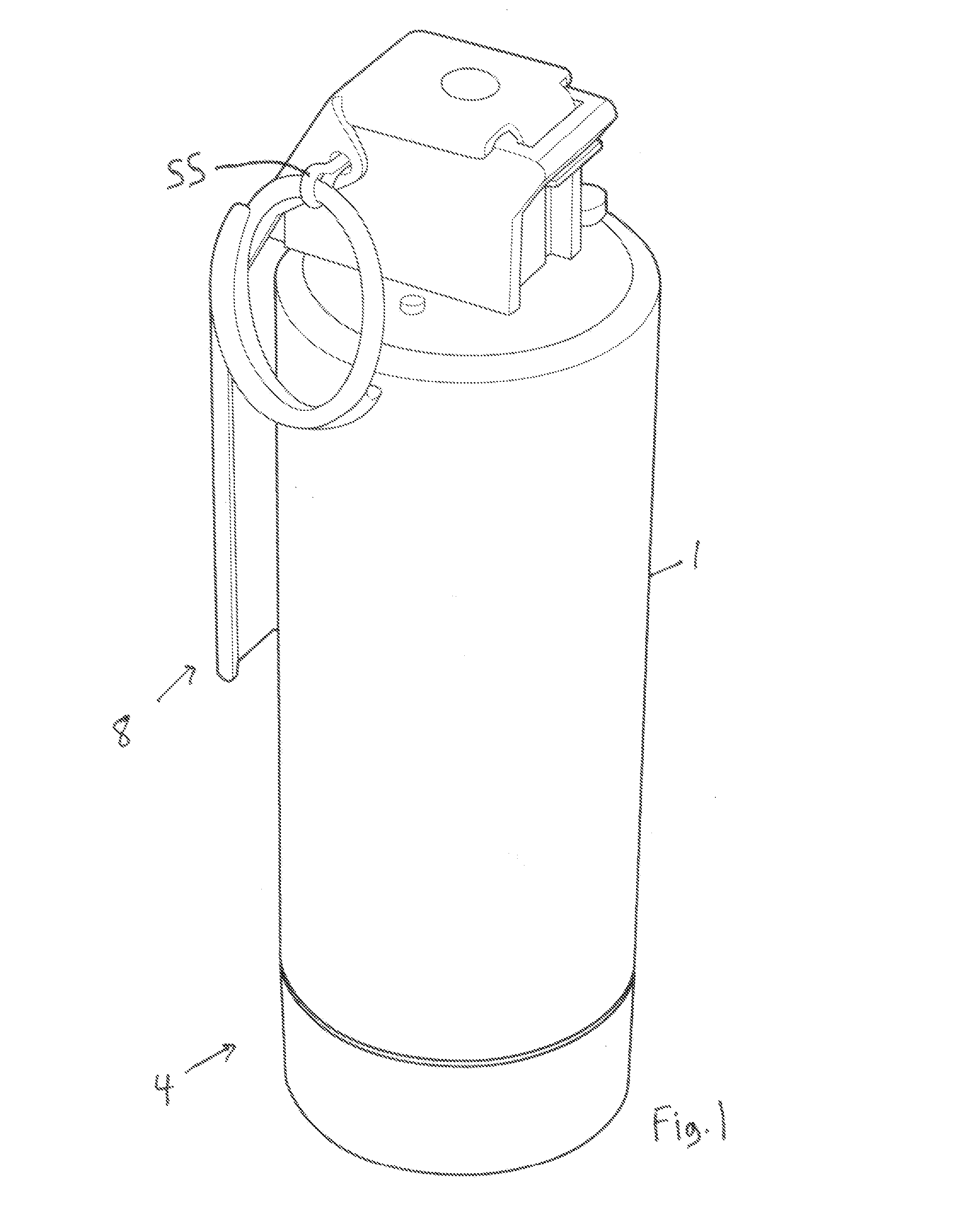
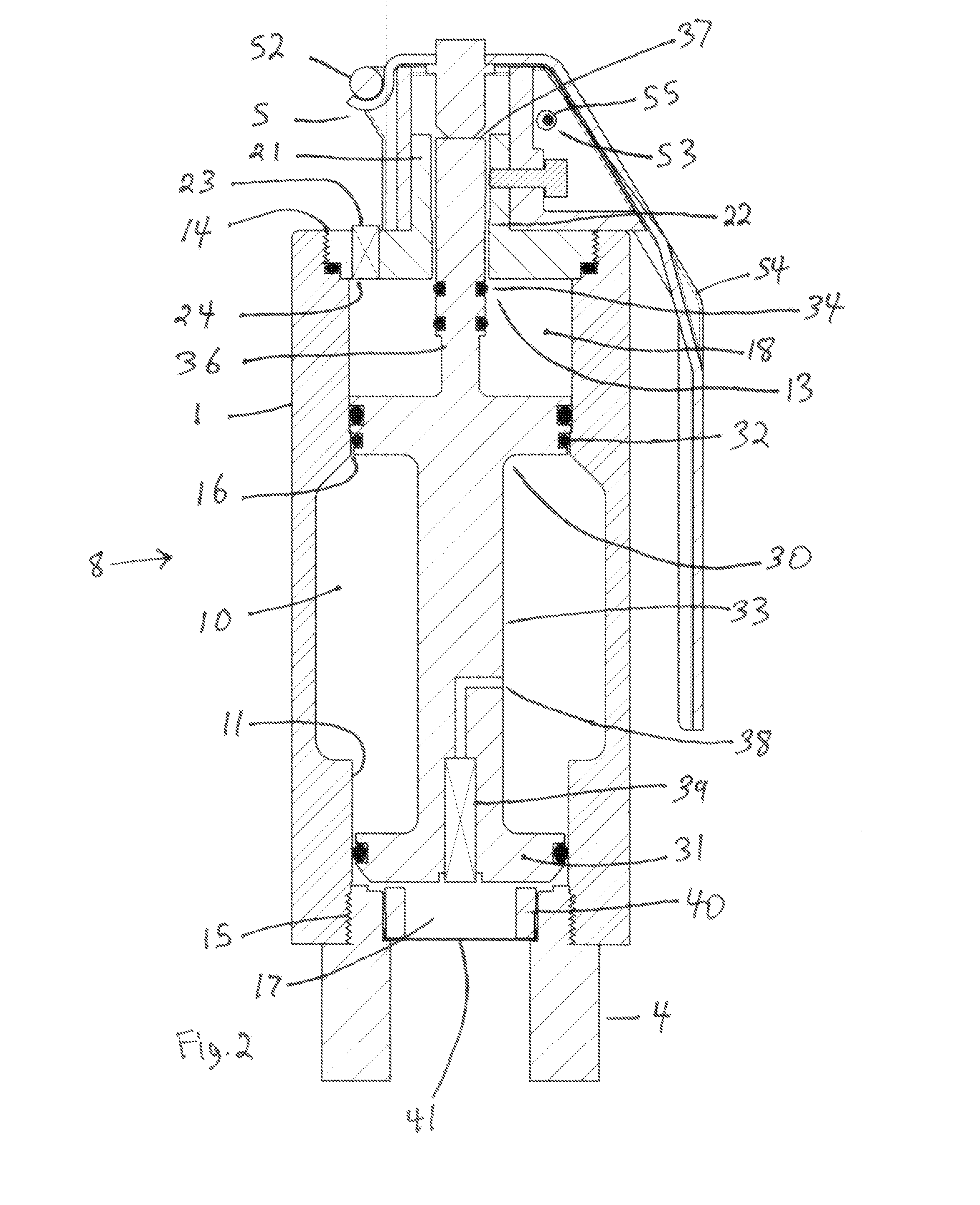
[0019]Referring firstly to FIG. 2, a simulator made in accordance with the present invention, shown generally as item 8, includes a housing 1 with threaded ends 14 and 15. The simulator further includes a pressure source 10 for pressurizing the discharge opening 17. Valve 31 is movable between a closed state where the valve prevents the flow of pressurized gas from reservoir 10 to discharge opening 17, and an open state as shown in FIG. 6. As shall be explained later, valve 31 is biased towards its open position by pneumatic pressure contained in gas reservoir 10. Trigger mechanism 5 includes a removable pin 55 inserted into hole 53. The removable handle 54 pivots around post 52 and is locked in place by pin 55.

[0020]Collar 21 has a passage 22 dimensioned to receive seal 34, seated on shaft 36 which is coupled to valve 31. When pin 55 remains in place in hole 53, the trigger mechanism 5 is placed into its locked state and it prevents valve 31 from moving into its open position. Furt...


PUM


Abstract

Here is disclosed a reusable pneumatic distraction device having a housing which encloses a first and a second gas reservoir which are configured to contain a quantity of high and low pressure gas, respectively. A valve member seals off an exhaust in the first gas reservoir, the valve member movable between a closed position sealing the exhaust and an open position. The device also includes a pneumatic drive for urging the valve towards its opened position. The pneumatic drive configured to apply a lower urging force followed by a larger urging force as the valve opens. The device is also provided with a lock pin releasably coupled to the valve for preventing the valve from moving towards its open position. Finally, the device includes a delay mechanism to delay the opening of the piston when the lock pin is released.

Description

CROSS REFERENCE TO RELATED APPLICATION[0001]This application claims priority from U.S. provisional patent application No. 61 / 559,843 dated Nov. 15, 2011, the entirety of which is incorporated herein by reference.FIELD OF THE INVENTION[0002]The invention relates generally to devices used to train military and law enforcement personnel in the deployment of non lethal distraction devices.BACKGROUND OF THE INVENTION[0003]Distraction devices which employ the use of explosives have been available for operational use for dangerous forced entry situations where law enforcement or military agents are faced with the prospect of entering an unknown area under fire. The proper usage of pyrotechnic distraction methods is of high importance to prevent injuries or fatalities of both agents and suspects within the areas agents are entering. Law enforcement and military agents are trained through a program of situational training where DDS may be used. These simulators can be dummy or inert placehol...

Claims


Application Information

Patent Timeline
IPC IPC(8): F41H9/06
CPCF41H9/06F41B11/80F42B8/26F42B12/36
Inventor CHONG, CARLTON
Owner CHONG CARLTON
Learn More