Remote-controlled cage trap door-opening mechanism

a remote control and cage trap technology, applied in the field of cage traps, can solve problems such as exposing users to unacceptably close encounters

Active Publication Date: 2014-07-15
WOODSTREAM CORP
View PDF61 Cites 14 Cited by
  • Summary
  • Abstract
  • Description
  • Claims
  • Application Information

AI Technical Summary

Benefits of technology

[0019]It is thus an object of the present invention to provide a remotely activated door-opening mechanism for a cage trap demonstrating mechanical and electronic simplicity for ease of opening the trap's door without requiring the user to have physical contact with the trap.
[0020]It is a further object of the present invention to provide a door-opening mechanism for a cage trap that is remotely controlled by a wireless IR transmitter to allow the user to maintain a safe distance from the trap when releasing a trapped animal.
[0022]It is yet another object of the present invention to provide a door-opening mechanism for a cage trap in accordance with the preceding objects and the first embodiment that can be easily attached to and then removed from the cage trap as an accessory, allowing the same mechanism to be moved from one trap to another for opening the respective doors thereof.
[0023]It is still another object of the present invention to provide a door-opening mechanism for a cage trap in accordance with the preceding objects that is relatively simple in electronic design while providing robust mechanical operation to open the trap door.
[0026]Additional objects of the invention include, for example, the provision of a door-opening mechanism for a cage trap which is durable, reliable and user friendly, and which can be manufactured from readily available components and in a cost-effective manner.

Problems solved by technology

When releasing a potentially dangerous animal, this may subject the user to an unacceptably close encounter when the animal exits the trap.

Method used


Image

  • Remote-controlled cage trap door-opening mechanism
  • Remote-controlled cage trap door-opening mechanism
  • Remote-controlled cage trap door-opening mechanism

Examples


first embodiment

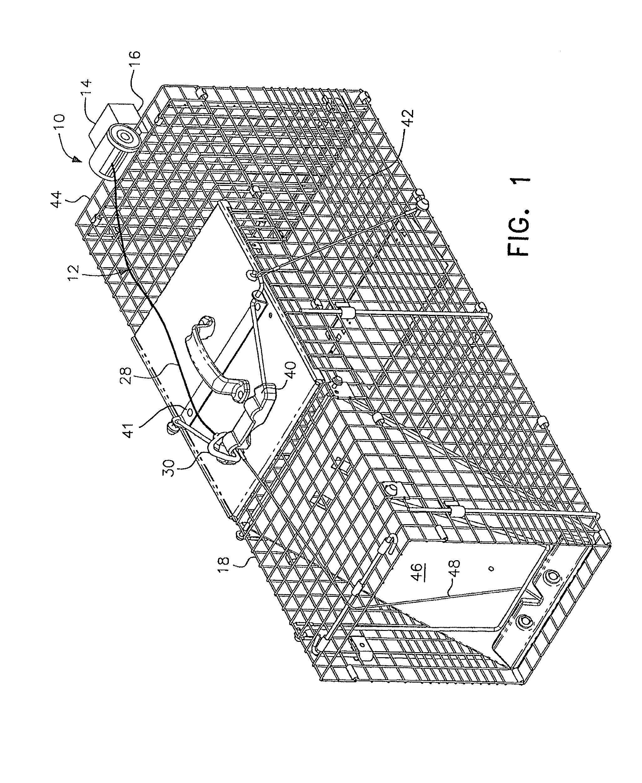
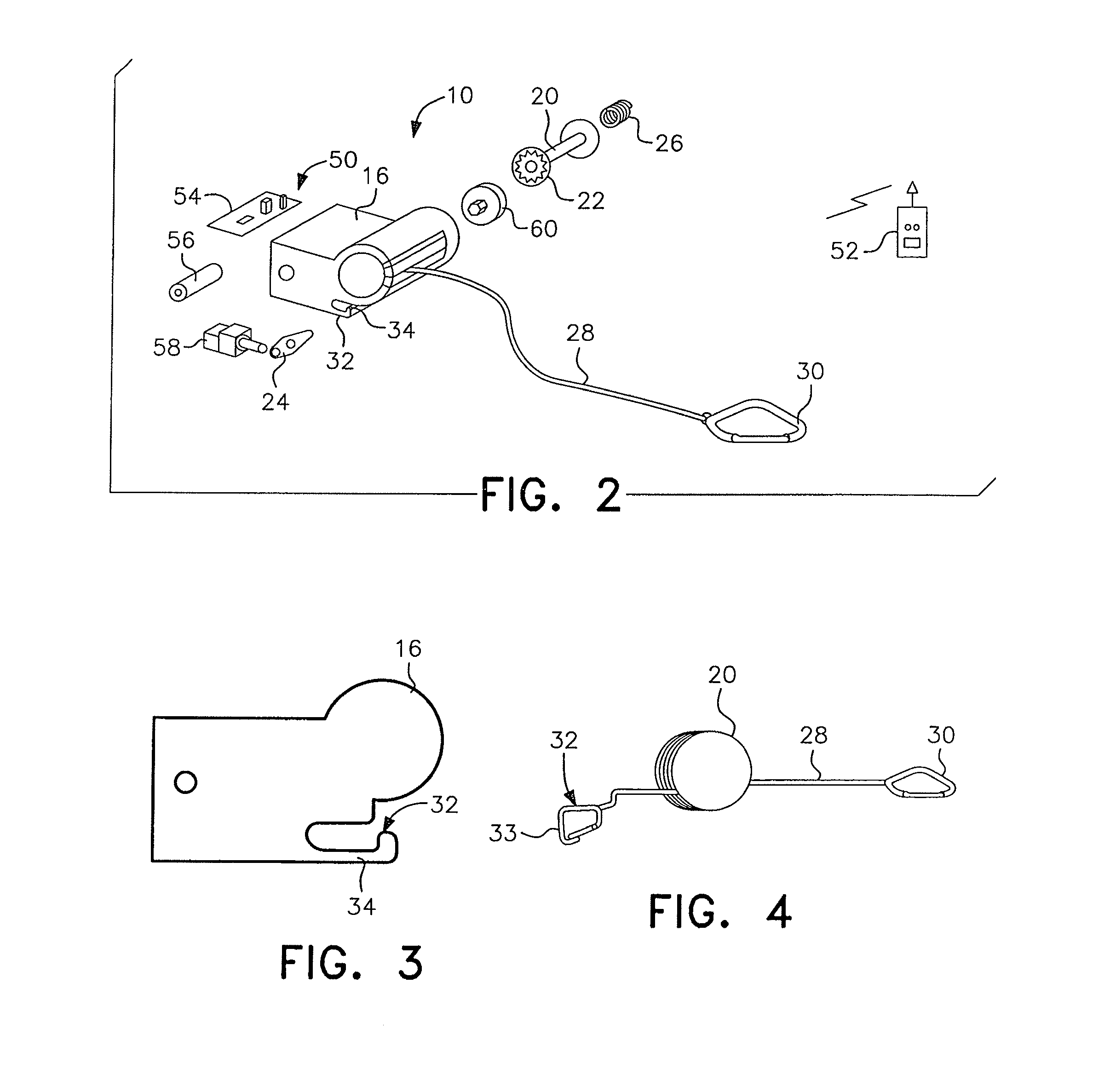
[0036]As shown in FIGS. 1 and 2, the remotely activated cage trap door-opening mechanism according to the present invention is generally designated by reference numeral 10 and is mounted at the top rear of a cage trap as disclosed in the aforesaid '085 application. The door opening mechanism 10 includes a mechanical assembly, generally designated by reference numeral 12, and an activating assembly, generally designated by reference numeral 14. The activating assembly and portions of the mechanical assembly are contained within a housing 16 which is mounted to the trap 18.

[0037]The mechanical assembly 12 includes a rotatable spool 20, a toothed sprocket 22, a latch pawl 24, a torsion / clock spring 26 and a cable 28 with a fastening element 30. The toothed sprocket 22 is mounted on one end of the spool 20 so as to ratchet against the latch pawl 24 within the housing. The torsion / clock spring 26 is mounted on the opposite end of the spool 20. The cable is wound on the spool 20 with the ...

second embodiment

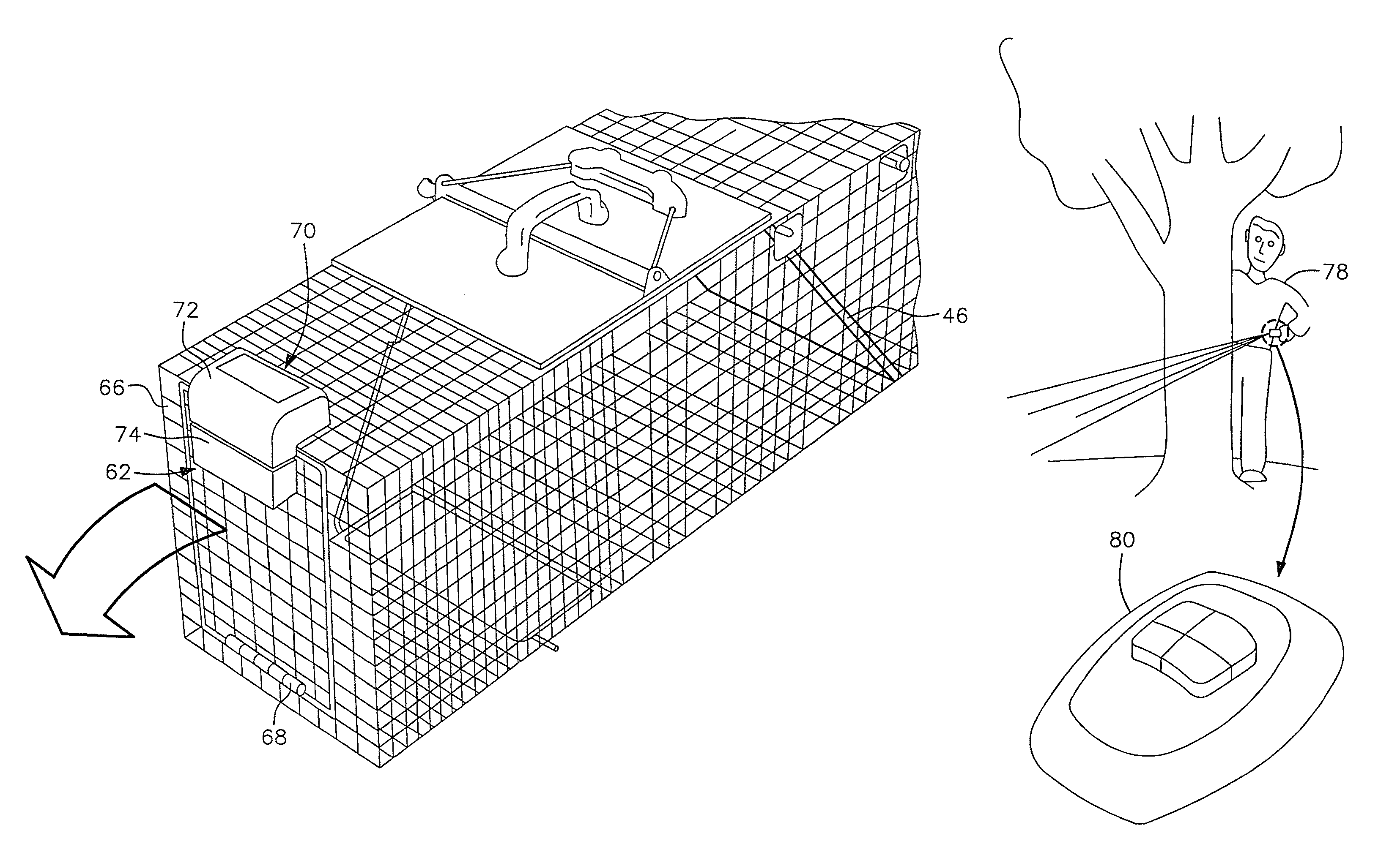
[0048]Any of the above-described assemblies for operation and activation of a remote door-opening mechanism may also be used in conjunction with a trap having a separate escape door such as that illustrated in FIGS. 5A and 5B and generally designated by reference numeral 62, in accordance with the present invention. The separate escape door 62 is preferably positioned at the opposite end of the trap relative to the entry door 46. Since the entry door 46 of the trap shown in FIG. 1 is described herein as being at the trap front end, then the separate escape door 62 is preferably at the rear end of the trap. Alternatively, the separate escape door could be positioned on the side of the trap, preferably near the rear end. Wherever its location, the separate escape door 62 may be more simply designed than the entry door, requiring only a movable panel that can be positioned and held in a closed position, as shown in FIG. 5A, to cover an escape opening 64, and then moved to an opened pos...


PUM


Abstract

A remotely activated door-opening mechanism is provided for a cage trap having an animal enclosure, preferably a cage trap as disclosed in U.S. Publ. No. US2008 / 0115405. The mechanism is mounted outside the enclosure of the trap and is preferably remotely activated by an IR or RF transmitter to open a door of the trap and release a trapped animal when the operator is at a safe distance away. The mechanism may also be manually set with a time delay and may be associated with either a main entry door to the trap or with a secondary escape door located at an opposite end of the trap.

Description

[0001]This application is a continuation of application Ser. No. 12 / 585,803 filed on Sep. 24, 2009, now U.S. Pat. No. 8,359,783, which claims the priority of U.S. Provisional application Ser. No. 61 / 136,676, filed Sep. 24, 2008.BACKGROUND OF THE INVENTION[0002]1. Field of the Invention[0003]This invention relates to cage-type animal traps of the kind generally used outdoors for trapping small to medium sized animals without harming the trapped animal.[0004]2. Description of the Prior Art[0005]Cage-type traps generally include a cage of metal wire mesh or the like with a door held open by a trigger mechanism until an animal is lured into the trap by suitable pre-inserted bait. After the animal enters the interior of the trap, the animal's weight pressed against the trigger actuates a trip which releases and closes the door, thereby trapping the animal inside the cage. A locking device serves to prevent the animal from opening the door from the inside.[0006]To release the trapped anim...

Claims


Application Information

Patent Timeline
Patent Type & Authority Patents(United States)
IPC IPC(8): A01M23/18A01M23/20A01M23/00A01M23/16
CPCA01M23/16A01M23/18A01M23/00A01M23/20
Inventor KAMERY, CHRISTOPHERLUBIC, MARKORICH, CHRISTOPHER T.
Owner WOODSTREAM CORP
Why Eureka
Try Eureka