Touch-sensitive display

Inactive Publication Date: 2014-05-15
KONE CORP
View PDF5 Cites 11 Cited by
  • Summary
  • Abstract
  • Description
  • Claims
  • Application Information

AI Technical Summary

Benefits of technology

[0015]As a result of the invention, the number of servicing visits required by a touch-sensitive display can be significantly reduced, the calibration

Problems solved by technology

One advantage of the piezoelectric sensors (piezo sensors) often used in touch-sensitive displays is their durability in use and also the fact that objects glued to the surface of the display element and the objects continually touching them do not prevent operation of the touch-sensitive display.
The sensors to be used in touch-sensitive displays are often susceptible to various error factors such as impacts, temperature fluctuations, deformation of components and humidity fluctuations.
Touch-sensitive displays are particularly susceptible to the aforementioned error factors in public spaces, such as e.g. in elevators.
In this case the sensors of a touch-sensitive display can lose their calibratio

Method used


Image

  • Touch-sensitive display
  • Touch-sensitive display
  • Touch-sensitive display

Examples


Embodiment Construction

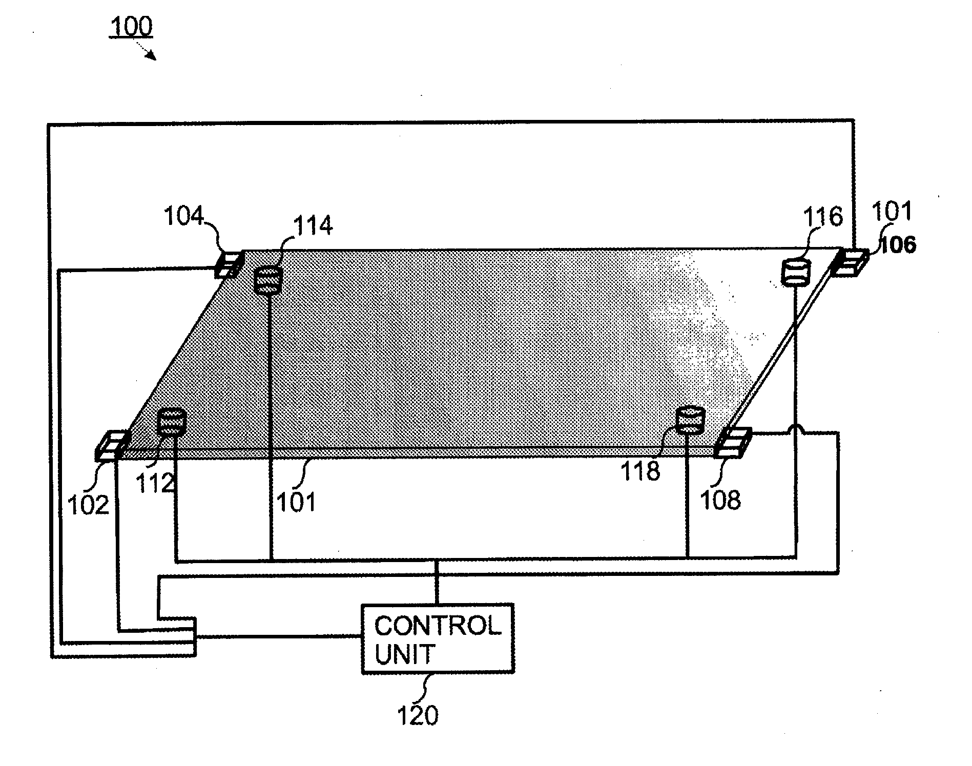
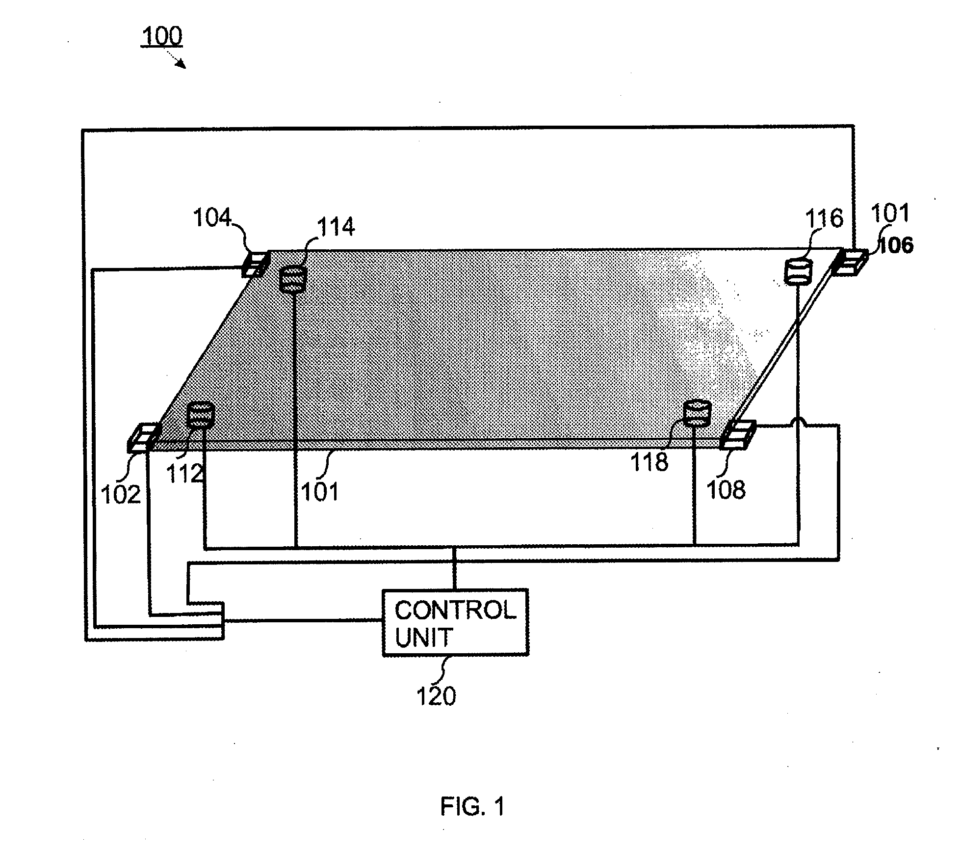
[0018]FIG. 1 presents a touch-sensitive display 100 according to the present invention. The touch-sensitive display 100 comprises a display element 101, in connection with which, preferably at the corners, are arranged or fixed force components 112, 114, 116 and 118. In FIG. 1 the display element 101 is described in a horizontal attitude, but from the viewpoint of the invention the attitude can be arbitrary. For calculating the position coordinates of the contact points, an X-Y coordinate system is “attached” to the display element, in which coordinate system the X-axis is e.g. in the direction of the longer edge of the display element and the Y-axis is in the direction of the shorter edge of the display element. The force components are disposed e.g. at the corners of the display element such that they are hidden inside the frame of the display element (the frame is not presented in FIG. 1). The force components are made e.g. of a piezoelectric material, which changes its shape und...


PUM


Abstract

The present invention discloses a method for the automatic calibrating of a touch-sensitive display, and also a touch-sensitive display. The touch-sensitive display comprises a display element, a plurality of force sensors for measuring the forces acting on the display element, and also a plurality of force components for producing forces acting on the display element. When a calibration need of the touch-sensitive display is verified, forces acting on the display element are produced with force components, the responses caused by the forces produced with the force components are measured with the force sensors, and calibration parameters are determined on the basis of the responses measured with the force sensors and on the basis of the position data of the force components.

Description

[0001]The present invention relates to touch-sensitive displays. More particularly the invention relates to the automatic calibration of touch-sensitive displays.BACKGROUND OF THE INVENTION[0002]Touch-sensitive displays are used to an ever-increasing degree in, among other things, mobile terminals, calculators, computers and in guidance and other such displays situated in public spaces. Touch-sensitive displays are formed, in terms of their structure, from an actual display element, e.g. from an LCD display, and also from sensors detecting the touch of a user, e.g. from piezoelectric sensors. The surface of the display element, which a user touches, is e.g. of glass. In these types of touch-sensitive displays the force or vibration produced by the touch of a user is detected with the aforementioned sensors that are in connection with the display element. The measuring signals produced by the sensors are conveyed to a control unit, which converts the measuring signals into position d...

Claims


Application Information

Patent Timeline
IPC IPC(8): G06F3/041
CPCG06F3/0418B66B1/463G06F3/04142G09G5/00G06F3/0414G06F3/0416
Inventor RUSANEN, NIKOINGMAN, CLAUS
Owner KONE CORP
Why Eureka
Try Eureka