Vacuum generation with a peripheral venturi

Inactive Publication Date: 2014-05-22
FORD GLOBAL TECH LLC
View PDF52 Cites 9 Cited by
  • Summary
  • Abstract
  • Description
  • Claims
  • Application Information

AI Technical Summary

Benefits of technology

[0004]In this way, vacuum may be generated by the peripheral venturi when the throttle is partially opened, e.g., at an angle that may not produce a sufficient pressure drop across the throttle to generate adequate vacuum in the intake manifold. The size of the venturi inlet and positioning relative to the throttle may be based on the throttle angle typically used during conditions where intake manifold vacuum is not sufficient, such as during the catalyst heating mode described above. By routing a portion of the intake air through the venturi, vacuum may be generated during conditions of low intake manifold vacuum.
[0005]The above advantages and other advantages,

Problems solved by technology

However, the engine intake manifold vacuum may not be sufficient for all of the subsystems at all operating conditions.
For example, during a catalyst heating mode immediately

Method used


Image

  • Vacuum generation with a peripheral venturi
  • Vacuum generation with a peripheral venturi
  • Vacuum generation with a peripheral venturi

Examples


Embodiment Construction

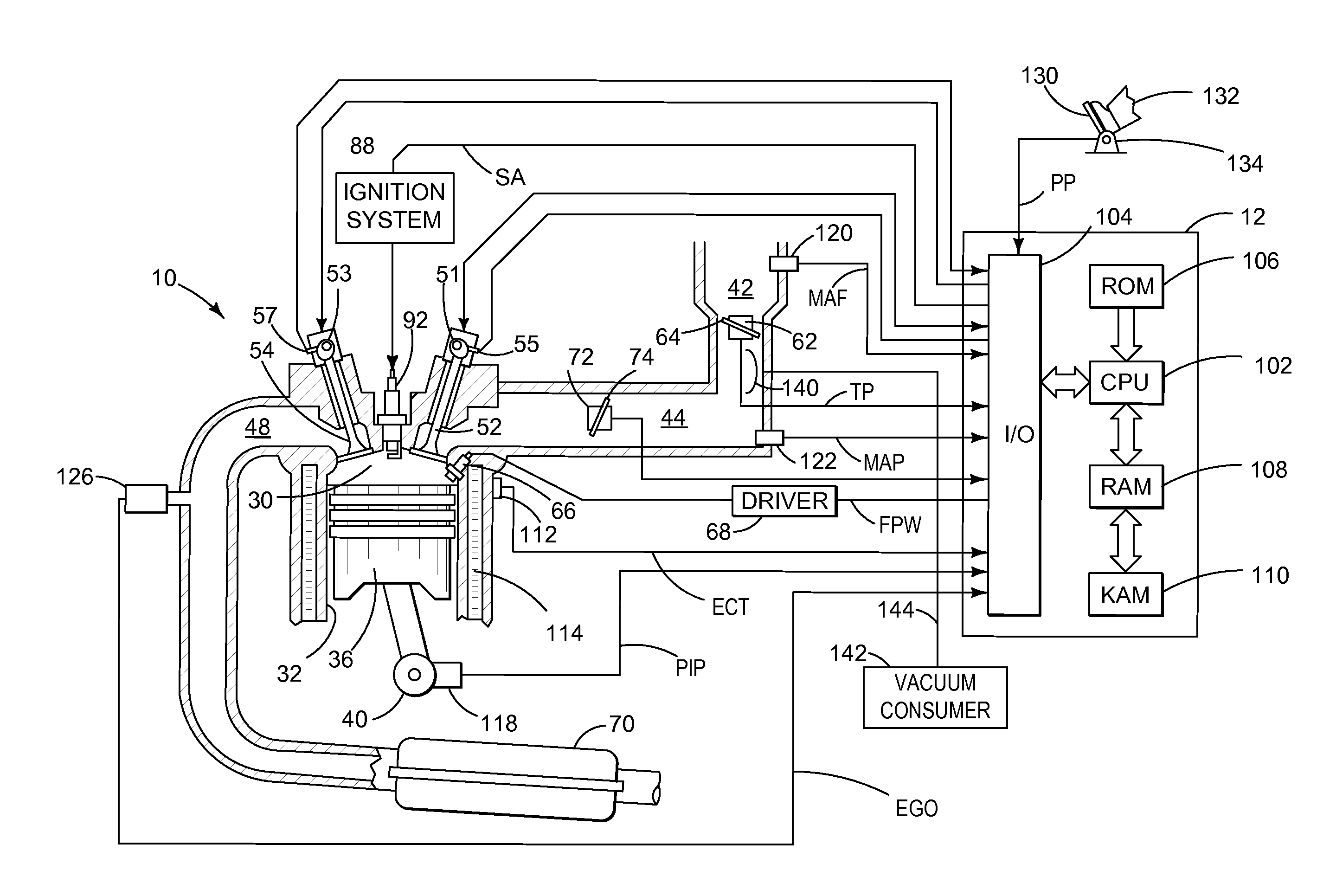
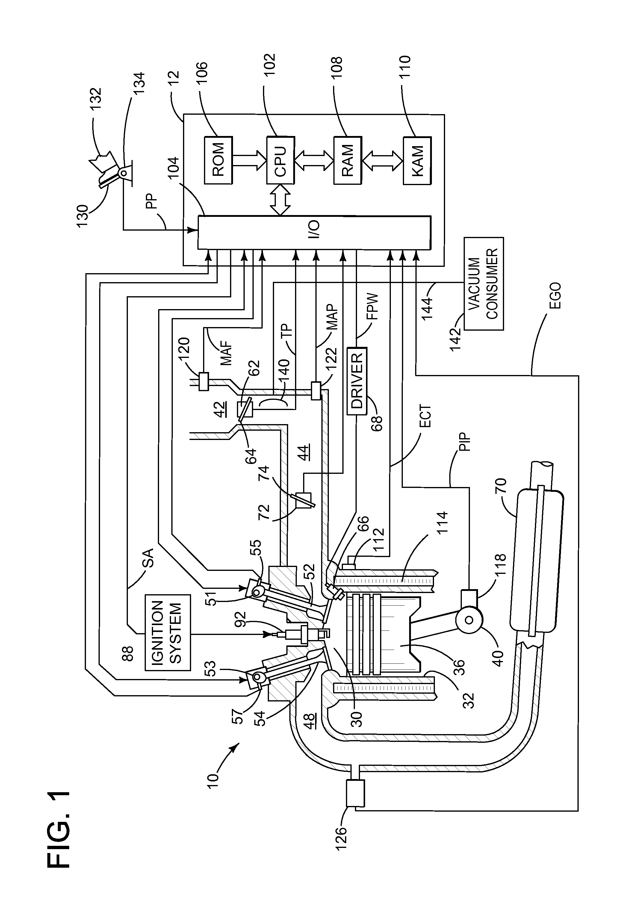
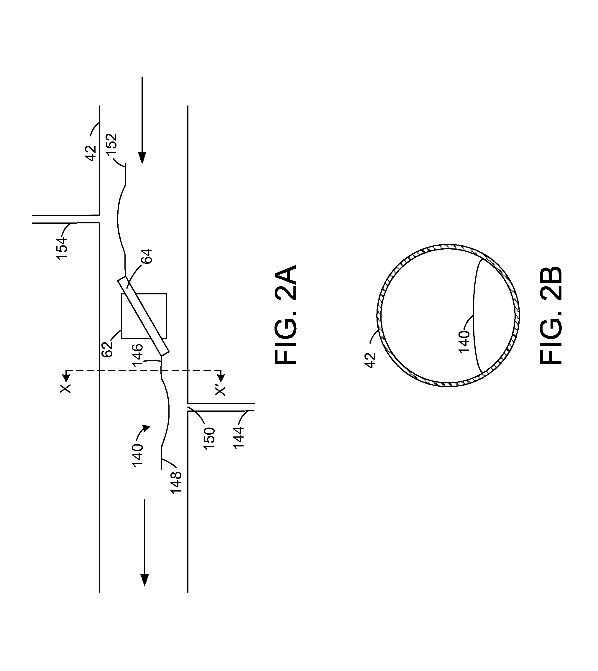
[0013]According to embodiments disclosed herein, a throttle body may include a high velocity passage incorporated into the inward opening side of the throttle body. The intake air may then flow through this passage at high velocity, resulting in a lower static pressure in this area relative to the rest of the intake manifold. A vacuum port is incorporated into the throttle body at the throat or exit of the high-velocity passage so that this vacuum can be routed to appropriate engine systems. The geometry of the high-velocity passage may be designed in such a manner that the air stream and vacuum generation is maximized at the throttle angles used during operating conditions that would otherwise not produce sufficient vacuum (e.g. during catalyst heating at altitude). An engine including a throttle body having a high velocity passage is illustrated in FIG. 1. FIGS. 2A and 2B illustrated the throttle body of FIG. 1 in greater detail. Methods for generating vacuum through the high-velo...


PUM


Abstract

Embodiments for generating vacuum at a throttle are presented. In one example, a system comprises a throttle positioned in an intake of an engine, and a peripheral venturi proximate the throttle, the venturi having an inlet positioned to interface with an edge of the throttle when the throttle is in a partially open position. In this way, vacuum may be generated by flow air through the venturi.

Description

FIELD[0001]The present disclosure relates to an internal combustion engine.BACKGROUND AND SUMMARY[0002]Multiple vehicle subsystems, such as the vehicle brakes, may utilize vacuum as an actuation force. The vacuum is typically supplied by the engine through a connection to the intake manifold, which is at sub-barometric pressure when the throttle is partially closed and regulating the airflow into the engine. However, the engine intake manifold vacuum may not be sufficient for all of the subsystems at all operating conditions. For example, during a catalyst heating mode immediately after engine starting, a high level of spark retard may be used to generate exhaust heat directed to the catalyst, resulting in insufficient vacuum from the intake manifold.[0003]The inventors have recognized the issues with the above approach and offer a system to at least partly address them. In one embodiment, a system comprises a throttle positioned in an intake of an engine, and a peripheral venturi p...

Claims


Application Information

Patent Timeline
IPC IPC(8): F02D9/08
CPCF02D9/08F02D9/1055
Inventor RUSS, STEPHEN GEORGE
Owner FORD GLOBAL TECH LLC
Why Eureka
Try Eureka