Integrated seat mounted inceptor

a seat and inceptor technology, applied in the field of aircraft control, can solve the problems of limited person's access to the seat, affecting the use of the cockpit space, and affecting the ability of the control system to work

Active Publication Date: 2014-05-22
SIKORSKY AIRCRAFT CORP
View PDF25 Cites 32 Cited by
  • Summary
  • Abstract
  • Description
  • Claims
  • Application Information

AI Technical Summary

Problems solved by technology

As aircraft systems become more complex, the useful space in the cockpit which is accessible to the pilots becomes more nearly filled with instruments, switches, etc.
A portion of conventional control systems is positioned adjacent the pilot's seat such that the control system is an obstacle when accessing or egressing the seat quickly, such as in emergency situations for example.
Not only does this positioning create a visual blockage, but it also limits the size of the person that may access the seat.

Method used


Image

  • Integrated seat mounted inceptor
  • Integrated seat mounted inceptor
  • Integrated seat mounted inceptor

Examples


Embodiment Construction

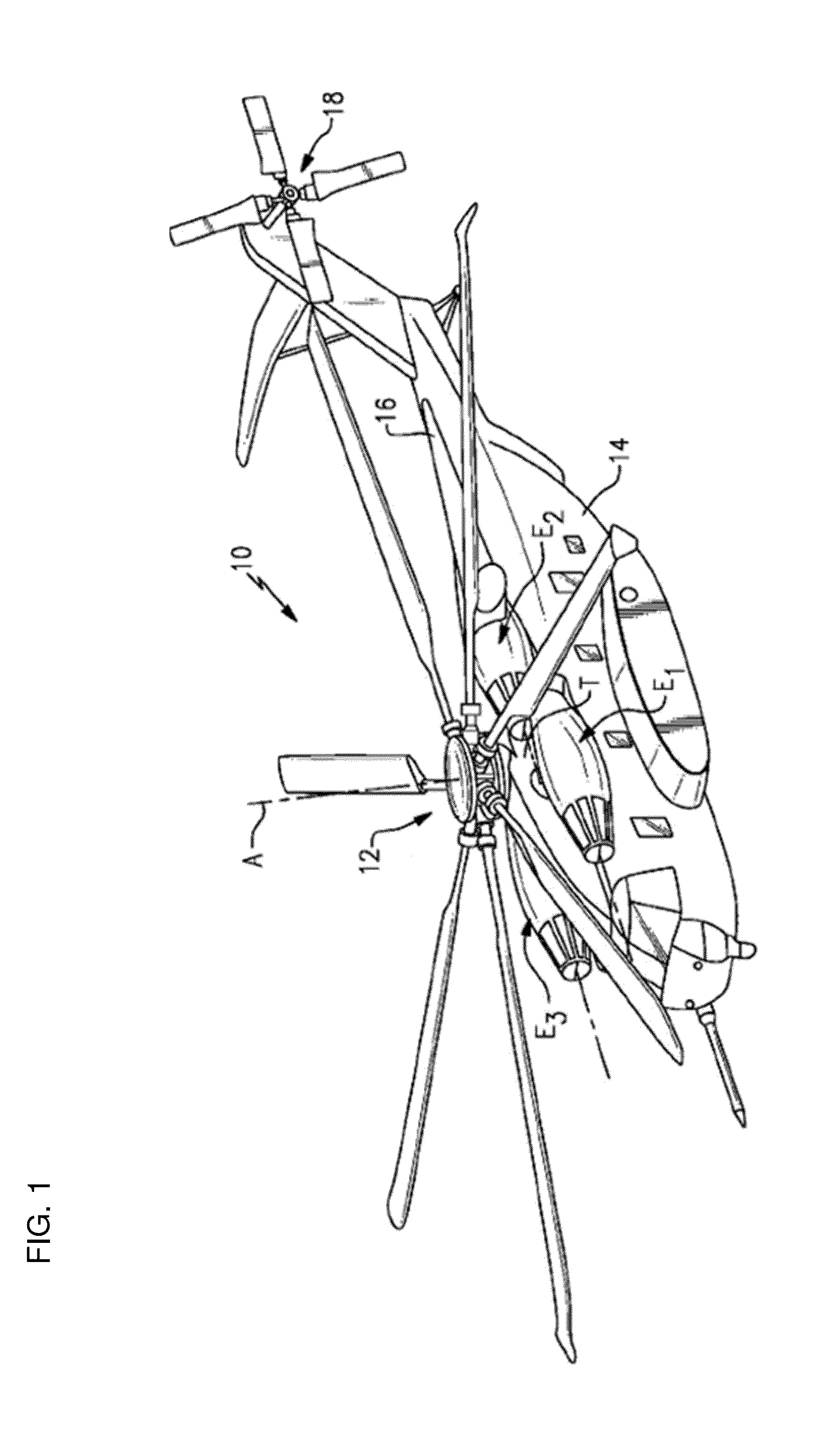
[0018]FIG. 1 schematically illustrates an exemplary vertical take-off and landing (VTOL) rotary wing aircraft 10. The rotary wing aircraft 10 in the disclosed, non-limiting embodiment includes a main rotor system 12 supported by an airframe 14 having an extended tail 16 which includes an anti-torque system 18, such as a tail rotor system for example. The main rotor system 12 is driven about an axis of rotation A through a main rotor gearbox (not shown) by one or more engines E. The main rotor system 12 includes a plurality of blades 30 connected to a rotor hub 20. The main rotor gearbox may be interposed between the one or more engines E, the main rotor system 12 and the anti-torque system 18. The main rotor gearbox is mechanically connected to the main rotor system 12 and to the anti-torque system 18 so that the main rotor system 12 and the anti-torque system 18 may both be driven by the main rotor gearbox. Although a particular rotary wing aircraft configuration is illustrated and...


PUM


Abstract

An inceptor is provided including a control stick mounted to a seat. The control stick is movable about at least a first axis. A fly-by-wire inceptor control system is housed within a portion of the seat. The inceptor control system is configured to provide input signal indicative of movement of the control stick to a flight control system.

Description

BACKGROUND OF THE INVENTION[0001]This invention relates generally to aircrafts, and more particularly, to an apparatus for controlling an aircraft.[0002]When in flight, an aircraft may be oriented about a plurality of axes. The aircraft's orientations may also be referred to as attitudes including pitch, roll and, yaw. In both fixed wing and rotary wing aircrafts, it is common for the pilot to use a variety of positionable controls, such as sticks, levers, wheels, and pedals to position the control surfaces of the aircraft, and thereby control the aircraft attitude, altitude, speed and the like. In the simplest of systems, the controls are connected by cables to the control surfaces, for example cables may connect control pedals to the rudder of a fixed wing aircraft. In more complicated systems, the controls may have mechanical connections which are boosted by hydraulic servos, or the like.[0003]As aircraft systems become more complex, the useful space in the cockpit which is acces...

Claims


Application Information

Patent Timeline
Patent Type & Authority Applications(United States)
IPC IPC(8): B64C13/04
CPCB64C13/04B64C13/0421B64C27/56
Inventor VAN STAAGEN, MICHAEL G.
Owner SIKORSKY AIRCRAFT CORP
Why Eureka
Try Eureka