
Antenna system with high isolation characteristics

an antenna system and isolation characteristic technology, applied in the field of antenna systems, can solve problems such as degrading the radiation performance of antennas

Active Publication Date: 2014-05-22
QUANTA COMPUTER INC
View PDF3 Cites 12 Cited by
  • Summary
  • Abstract
  • Description
  • Claims
  • Application Information

AI Technical Summary

Benefits of technology

The patent is about an antenna system that includes two antennas and a band rejection filter. The band rejection filter has a unique design that includes a protruded ground element and two additional branches that form coupling gaps with each other. The antennas and the band rejection filter are all placed on a dielectric substrate. The technical effect of this design is the creation of a high-quality antenna system that has good band isolation, meaning the two antennas can communicate with each other without interference from other signals.

Problems solved by technology

Since these antennas are close to each other, mutual interference is generated, and the radiation performance thereof is degraded.

Method used


Image

  • Antenna system with high isolation characteristics
  • Antenna system with high isolation characteristics
  • Antenna system with high isolation characteristics

Examples


Embodiment Construction

[0017]In order to illustrate the purposes, features and advantages of the invention, the embodiments and figures thereof in the invention are shown in detail as follows.

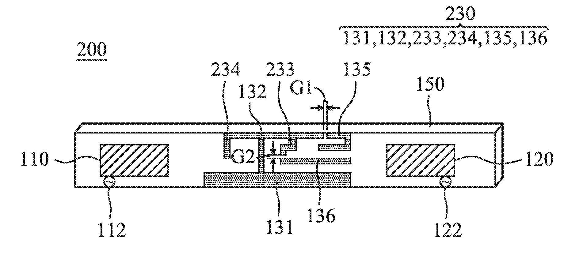
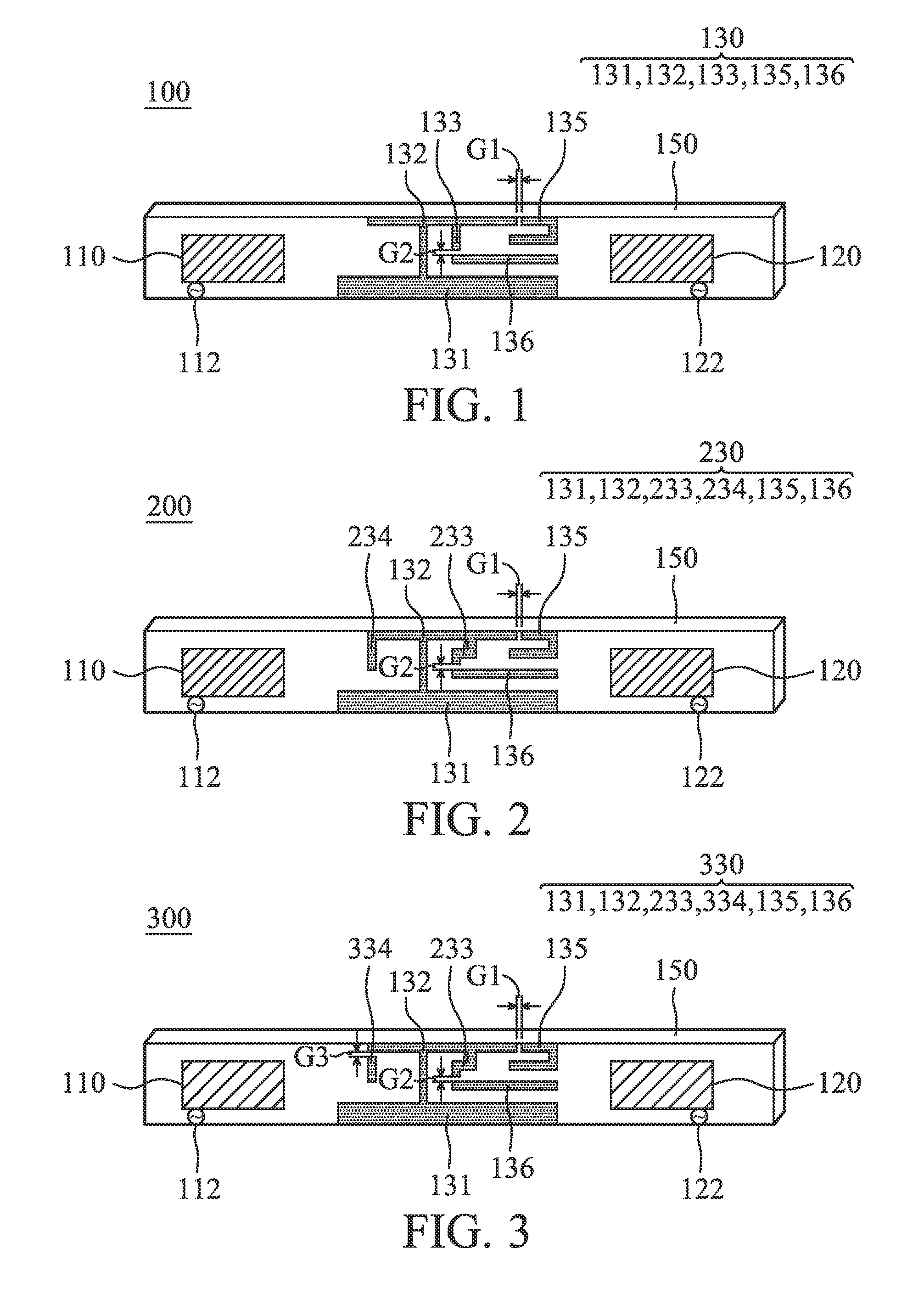
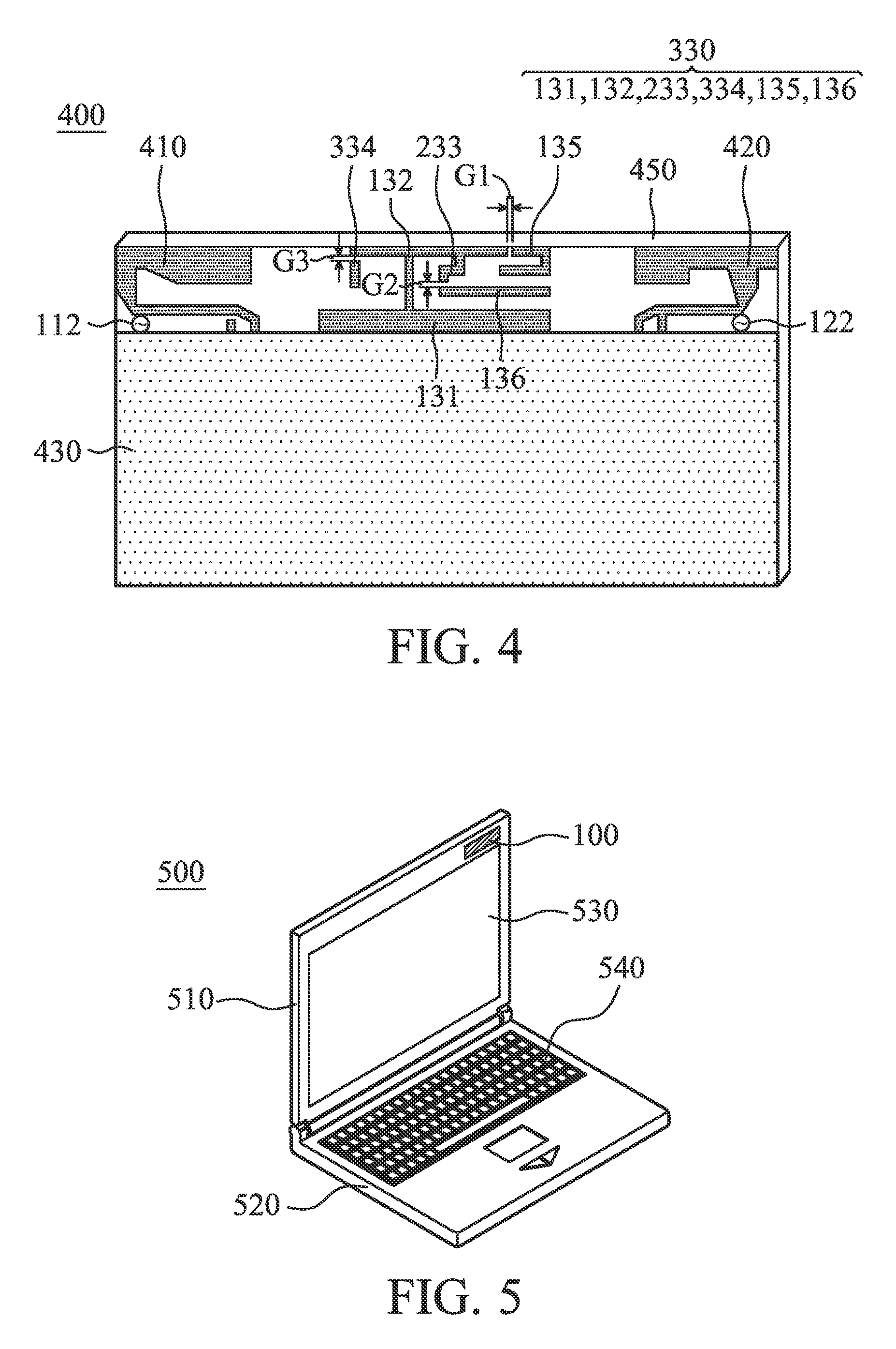
[0018]FIG. 1 is a diagram for illustrating an antenna system 100 according to an embodiment of the invention. The antenna system 100 may be disposed in a variety of mobile devices, for example, a tablet computer or a notebook computer. As shown in FIG. 1, the antenna system 100 comprises a first antenna 110, a second antenna 120, a band rejection filter 130, and a dielectric substrate 150 (or a printed circuit board 150). The first antenna 110 is coupled to a first signal source 112, and the second antenna is coupled to a second signal source 122. The first antenna 110 and the second antenna 120 may operate in at least one same band, for example, a WLAN (Wireless Local Area Networks) band, a Bluetooth band, and a WWAN (Wireless Wide Area Networks) band, or an LTE (Long Term Evolution) band. Note that the types of the...


PUM


Abstract

An antenna system includes a first antenna, a second antenna, a band rejection filter, and a dielectric substrate. The band rejection filter is substantially disposed between the first antenna and the second antenna. The band rejection filter includes a protruded ground element, a main branch, a first extension branch, a first additional branch, and a second additional branch. The main branch substantially has a T-shape. The first extension branch is coupled to the main branch. The first additional branch is separated from the main branch, and a first coupling gap is formed between the first additional branch and the main branch. The second additional branch is separated from the main branch, and a second coupling gap is formed between the second additional branch and the first extension branch. The band rejection filter is configured to improve the isolation between the first antenna and the second antenna.

Description

CROSS REFERENCE TO RELATED APPLICATIONS[0001]This Application claims priority of Taiwan Patent Application No. 101143189 filed on Nov. 20, 2012, the entirety of which is incorporated by reference herein.BACKGROUND OF THE INVENTION[0002]1. Field of the Invention[0003]The disclosure generally relates to an antenna system, and more particularly, relates to an antenna system with high isolation characteristics.[0004]2. Description of the Related Art[0005]With progress in mobile communication technology, mobile devices, for example, portable computers, mobile phones, tablet computer, multimedia players, and other hybrid functional portable electronic devices, have become more common To satisfy the demand of users, mobile devices usually can perform wireless communication functions. Some functions cover a large wireless communication area, for example, mobile phones using 2G, 3G, and LTE (Long Term Evolution) systems and using frequency bands of 700 MHz, 850 MHz, 900 MHz, 1800 MHz, 1900 M...

Claims


Application Information

Patent Timeline
Patent Type & Authority Applications(United States)
IPC IPC(8): H01Q21/28
CPCH01Q1/2266H01Q1/521H01Q21/28
Inventor LO, WEN-YUANLIN, HUIKUO, CHAO-HUNGJAO, JUI-CHUN
Owner QUANTA COMPUTER INC
Learn More