Multi-sector antenna structure

a multi-sector antenna and antenna structure technology, applied in the direction of antennas, antenna details, radiating element housings, etc., can solve the problems of random phase shift between multiple signal paths, receivers may not be able to successfully receive and decode original signals, and the system of iso is vulnerable to problems

Active Publication Date: 2014-05-22
RPX CORP
View PDF3 Cites 22 Cited by
  • Summary
  • Abstract
  • Description
  • Claims
  • Application Information

AI Technical Summary

Benefits of technology

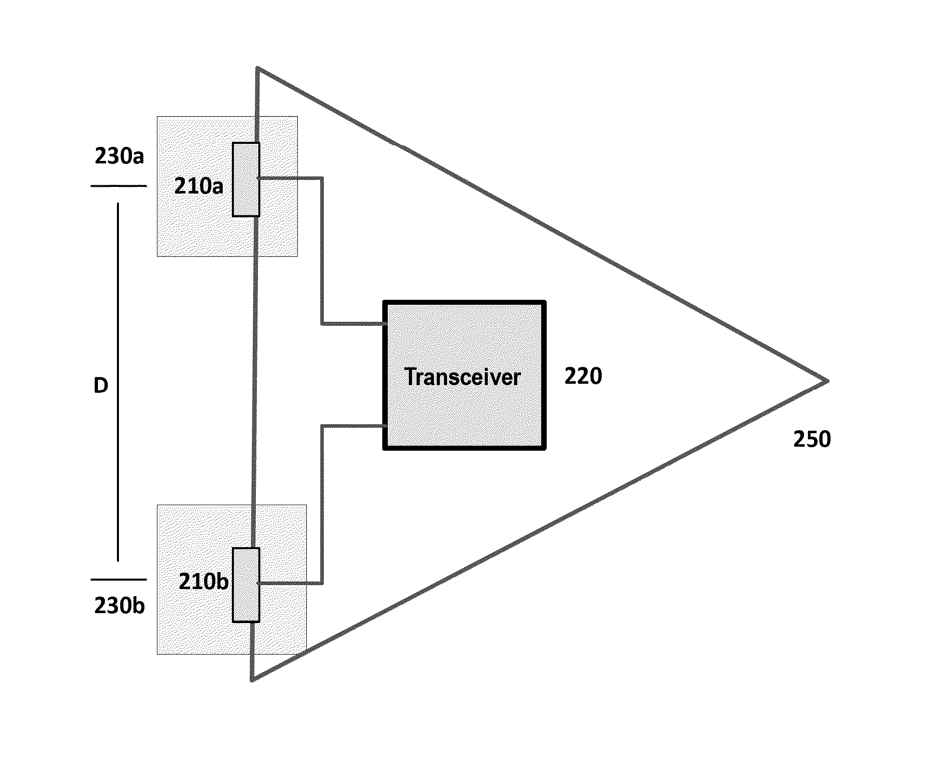
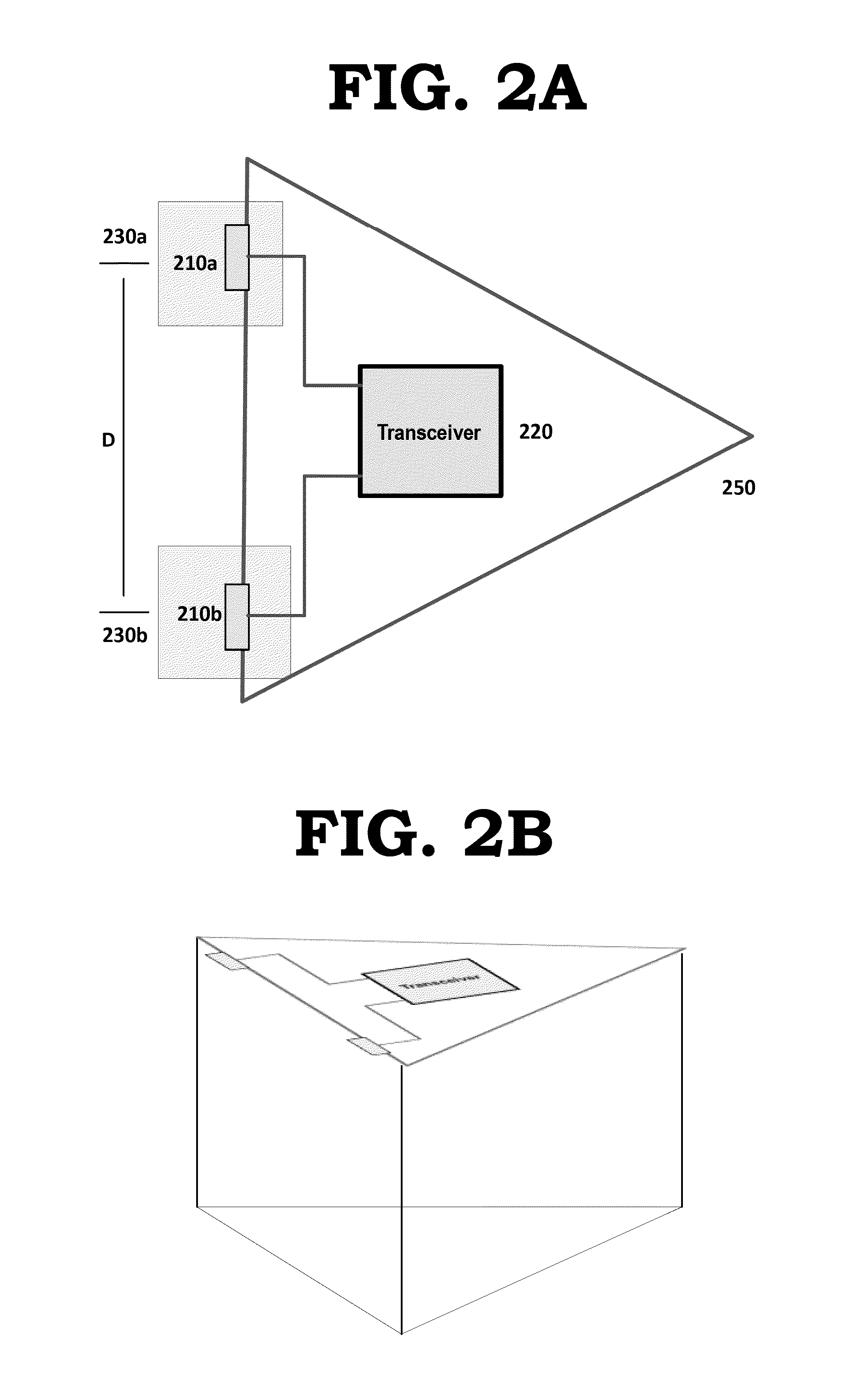
[0040]In one embodiment, the first antenna that is connected to the first transceiver group and third antenna that is connected to the second transceiver group together utilize antenna cross connect to provide redundancy and diversity to the first sector.

Problems solved by technology

While relatively simple to design, SISO systems are vulnerable to problems caused by multipath fading effects.
Multipath fading effects result when an electromagnetic field (EM field) meets obstructions such as hills, canyons, buildings, and utility wires, which results in the EM field scattering (reflecting), and thus taking multiple paths to reach its destination, resulting in random phase shifts between the multiple signal paths.
When the attenuation is severe, the signal may be below the receiver's minimum discernible signal level, and the receiver may not be able to successfully receive and decode the original signal.
In a wireless telecommunications system, such multipath fading can cause a reduction in coverage area, a reduction in achievable data speeds and an increase in the number of errors in processing the signal.
This minimum distance between the antenna arrays makes the use of a single integrated structure, such as a radome, to house the two antenna arrays impractical because a structure of such size may be visually imposing, heavy and may create a large surface area that is susceptible to wind loading.
Therefore, the installation of multiple antenna arrays using spatial diversity generally requires multiple structural enclosures (e.g., separate radomes) resulting in increased costs and more complex installations when compared to single enclosures.

Method used


Image

  • Multi-sector antenna structure
  • Multi-sector antenna structure
  • Multi-sector antenna structure

Examples


Embodiment Construction

[0058]While example embodiments are capable of various modifications and alternative forms, embodiments thereof are shown by way of example in the drawings and will herein be described in detail. It should be understood, however, that there is no intent to limit example embodiments to the particular forms disclosed, but on the contrary, example embodiments are to cover all modifications, equivalents, and alternatives falling within the scope of the claims. Like numbers refer to like elements throughout the description of the figures.

[0059]Methods discussed below may be implemented by hardware, software, firmware, middleware, microcode, hardware description languages, or any combination thereof. When implemented in software, firmware, middleware or microcode, the program code or code segments to perform the necessary tasks may be stored in a machine or computer readable medium such as a storage medium. A processor(s), Field Programmable Gate Array (FGPA) or an Application Specific In...


PUM


Abstract

A multiple sector cell-site antenna includes a first antenna oriented to serve a first sector, the first antenna electrically connected to a first transceiver group; a second antenna oriented to serve a second sector adjacent to the first sector, the second antenna electrically connected to the first transceiver group; and a single enclosure covering both the first antenna and the second antenna. By providing at least two multiple sector cell-site antennas in a system, the total number of enclosures is reduced while providing redundancy and diversity within the cells.

Description

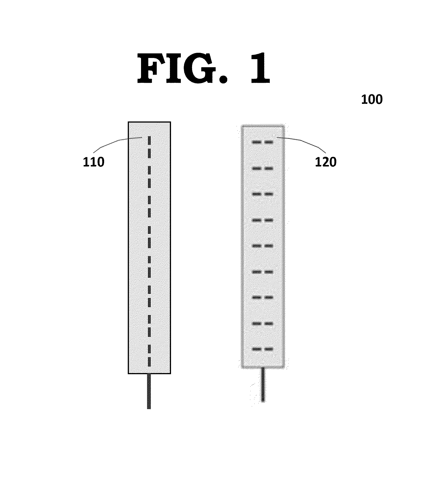
BACKGROUND OF THE INVENTION[0001]1. Field[0002]Embodiments relate to a multi-sector antenna, a multi-band multi-sector antenna, and systems including the same.[0003]2. Related Art[0004]In a wireless telecommunications system, a geographic area serviced by the wireless telecommunications system is divided into spatially distinct areas called “cells”. Cells are typically further divided into multiple ‘sectors’. For example, often each of the cells are divided into three equal area sectors. Typically, each cell contains a base transceiver station (BTS) that uses transceivers (TRXs) and antennas to facilitate wireless communication between user equipment (UE) and a network. The transceivers may include one or more receivers and transmitters and may be packaged in a Remote Radio Heads (RRHs). A RRH generally contains two or more transceivers that are each connected to a duplex filter, thus enabling each transceiver to support simultaneous downlink transmission and uplink reception via a ...

Claims


Application Information

Patent Timeline
Patent Type & Authority Applications(United States)
IPC IPC(8): H01Q21/28
CPCH01Q1/246H01Q21/08H01Q21/28H04W16/28
Inventor SOLONDZ, MAX
Owner RPX CORP
Why Eureka
Try Eureka