
Multi-hop error recovery

a multi-hop error and recovery technology, applied in the field of computer networking, can solve the problems of wasting bandwidth, packet progress made before dropping, and packet loss,

Active Publication Date: 2014-05-22
INTEL CORP
View PDF5 Cites 165 Cited by
  • Summary
  • Abstract
  • Description
  • Claims
  • Application Information

AI Technical Summary

Benefits of technology

The patent text discusses a network architecture and network switches that support enhanced network performance using multi-hop forwarding with error recovery. The technical effects of this invention include improved network speed, reduced latency, and better network resilience against failures. The invention also addresses the issue of packet loss due to bit errors, congestion, or switch failures by introducing reliable protocols and error correcting codes. Overall, the invention improves network performance and reliability.

Problems solved by technology

In computer networks, packets may be lost due to due to various reasons, including bit errors, congestion, or switch failures.
When a packet is lost on a path between a source and its destination, it typically needs to be retransmitted from the source.
First, since the path from source to destination is reasonably long, it takes a long time for the source to find out that a packet has been lost.
Second, the progress the packet made before getting dropped is wasted bandwidth.
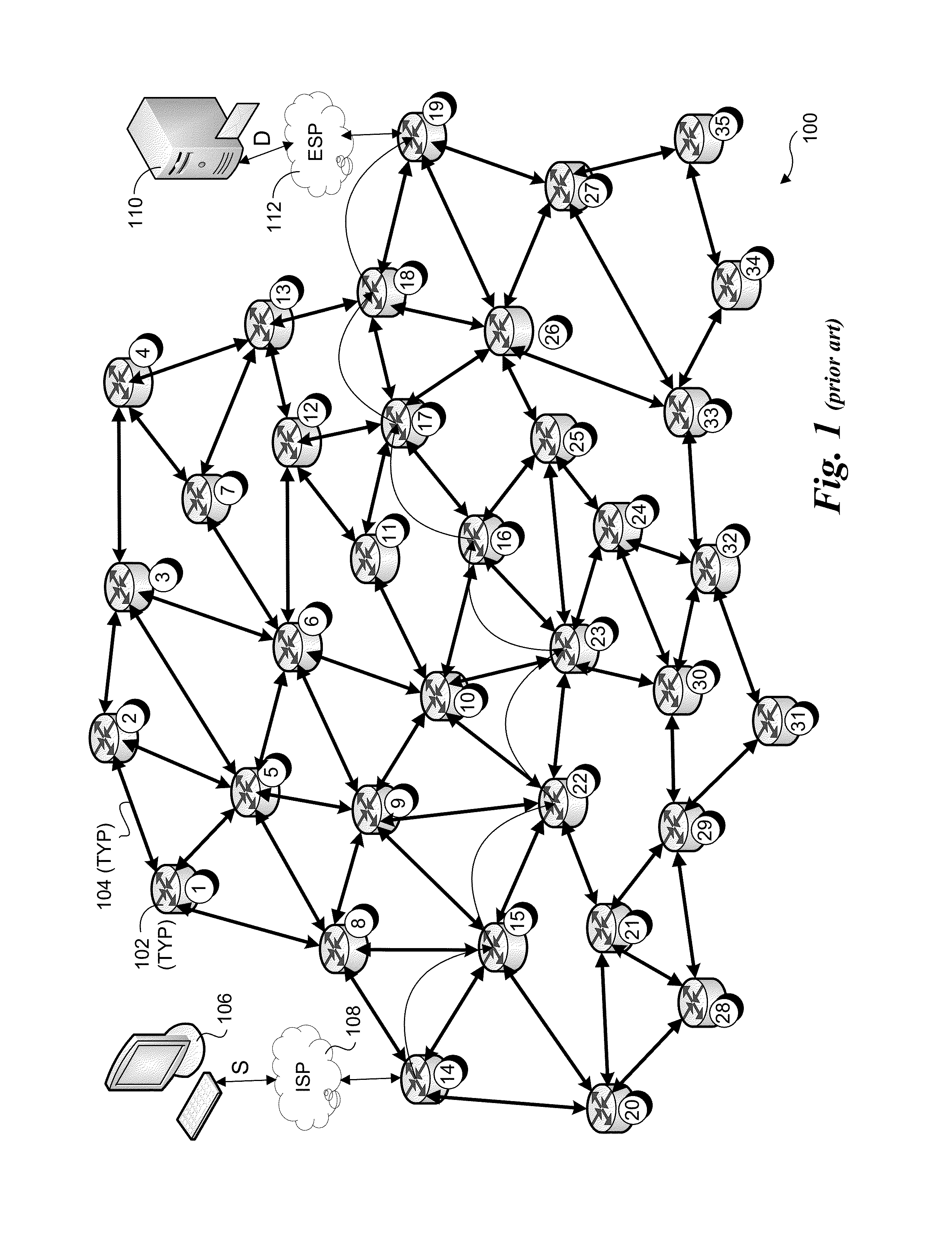
On lossy links with many bit errors, hop-by-hop reliability is sometimes done.
This requires more complex and expensive switches, since it requires more buffers for S1 to hold onto packets until receiving an acknowledgement from S2.
This has a lot of overhead, both in terms of extra checksum bits, and computation, and there is still the possibility that there are more errors than can be handled by the error correcting code.
As previously noted, the problem with dropping packets is that a packet that has already traveled several hops towards the destination must be retransmitted again from the source, so that amount of bandwidth has been wasted.
Also, the end-to-end delay for the source to discover the packet has been dropped can be long, because information about whether a packet has been received needs to be communicated from the destination.
The problem with doing backpressure the way it is traditionally done (e.g., Infiniband or Data Center Bridging) is that congestion can spread; a single slow resource (e.g., a destination) can have its packets occupy all the buffers in a switch, and since the switch is not allowed to drop those, the switch must refuse to receive any more packets (for that class), even though those new packets may not be travelling towards the congested resource.
This in turn can cause buffers to become full in adjacent switches, etc.

Method used


Image

  • Multi-hop error recovery
  • Multi-hop error recovery
  • Multi-hop error recovery

Examples


Embodiment Construction

[0029]Embodiments of methods and apparatus for enhancing network performance using Hop-by-Hop forwarding with error recovery are described herein. In the following description, numerous specific details are set forth to provide a thorough understanding of embodiments of the invention. One skilled in the relevant art will recognize, however, that the invention can be practiced without one or more of the specific details, or with other methods, components, materials, etc. In other instances, well-known structures, materials, or operations are not shown or described in detail to avoid obscuring aspects of the invention.

[0030]Reference throughout this specification to “one embodiment” or “an embodiment” means that a particular feature, structure, or characteristic described in connection with the embodiment is included in at least one embodiment of the present invention. Thus, the appearances of the phrases “in one embodiment” or “in an embodiment” in various places throughout this spec...


PUM


Abstract

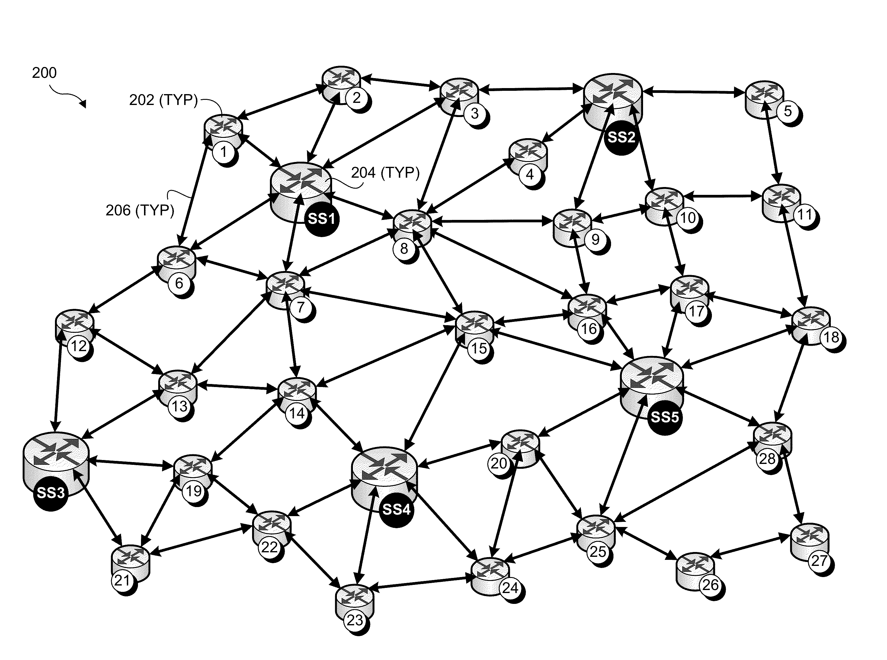
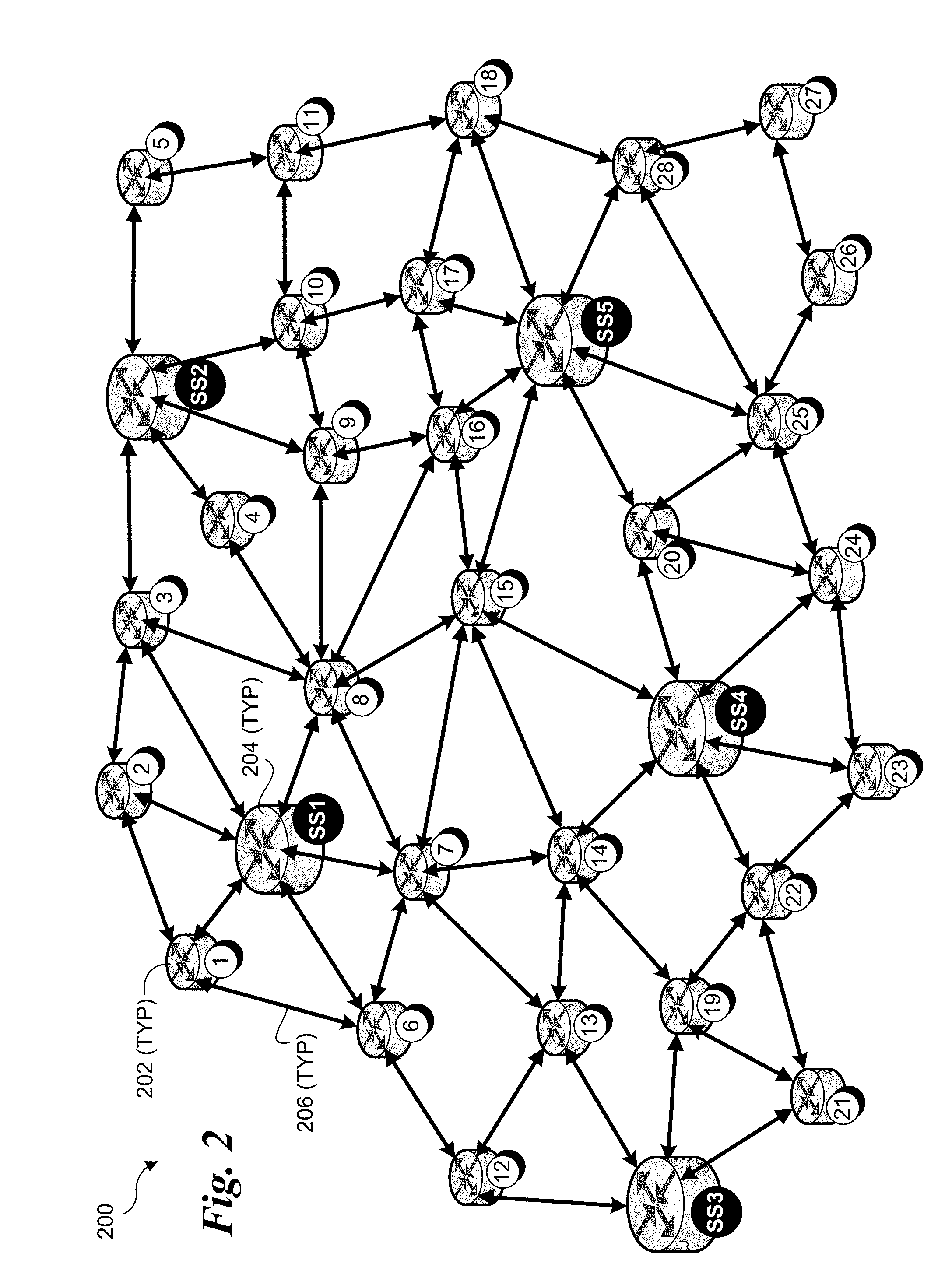
Methods, apparatus and network architectures relating to the use of a Hop-by-Hop packet forwarding technique using “stepping stone” switches. The network architectures include use of stepping stone switches interspersed with non-stepping stone switches such as conventional network switches comprising network elements such switches, routers, repeaters, etc. The stepping stone switches are configured to route packets as multiplexed flows along tunneled sub-paths between stepping stone switches in a hop-by-hop manner with error recovery, as opposed to conventional routing under which packets are routed from a source to a destination using an arbitrary path or along a (generally) lengthy flow-based path. Accordingly, packets from a source endpoint are routed to a destination endpoint via multiple sub-paths connecting pairs of stepping stone switches, with each sub-path traversing one or more conventional switches and constituting a logical Hop in the Hop-by-Hop route.

Description

FIELD OF THE INVENTION[0001]The field of invention relates generally to computer networking and, more specifically but not exclusively relates to a network architecture and network switches supporting enhanced network performance using multi-hop forwarding with error recovery.BACKGROUND INFORMATION[0002]Ever since the introduction of the microprocessor, computer systems have been getting faster and faster. In approximate accordance with Moore's law (based on Intel® Corporation co-founder Gordon Moore's 1965 publication predicting the number of transistors on integrated circuits to double every two years), the speed increase has shot upward at a fairly even rate for nearly three decades. At the same time, the size of both memory and non-volatile storage has also steadily increased, such that many of today's personal computers are more powerful than supercomputers from just 10-15 years ago. In addition, the speed of network communications has likewise seen astronomical increases.[0003...

Claims


Application Information

Patent Timeline
Patent Type & Authority Applications(United States)
IPC IPC(8): H04L12/56H04L45/28
CPCH04L45/38H04L12/4633H04L45/26
Inventor PERLMAN, RADIA
Owner INTEL CORP
Learn More