Ground terminal and connector provided therewith

a ground terminal and connector technology, applied in the direction of connection contact material, two-part coupling device, coupling device connection, etc., can solve the problems of reducing the integrated density, degrading the cutting layout, complicated shape, etc., and achieves good cutting layout and small installation area

Active Publication Date: 2014-05-22
ORMON CORP
View PDF8 Cites 18 Cited by
  • Summary
  • Abstract
  • Description
  • Claims
  • Application Information

AI Technical Summary

Benefits of technology

[0007]The present invention has been devised to solve the problems described above, and provides an easy-to-produce ground terminal having a small installation area and a good cutting layout and a connector provided therewith.

Problems solved by technology

Therefore, unfortunately a wide installation area is required when the annular ground terminal is assembled in the printed board, integrated density is lowered, a cutting layout is degraded, the shape is complicated, and the production is not easily performed.

Method used


Image

  • Ground terminal and connector provided therewith
  • Ground terminal and connector provided therewith
  • Ground terminal and connector provided therewith

Examples


first embodiment

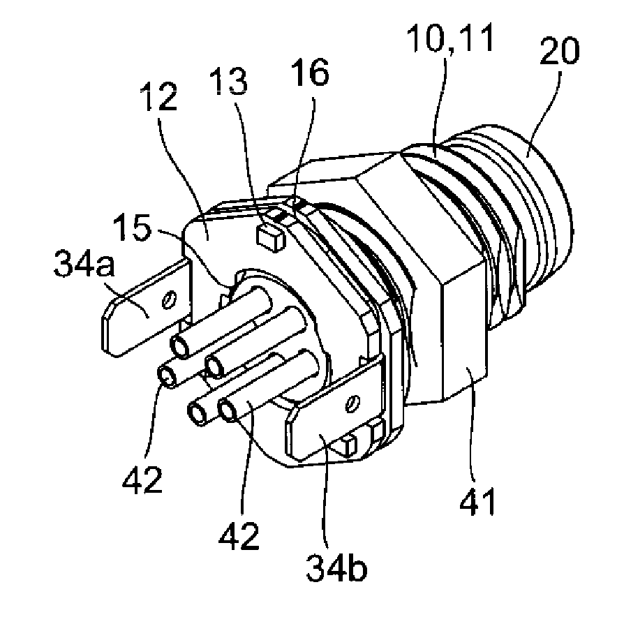
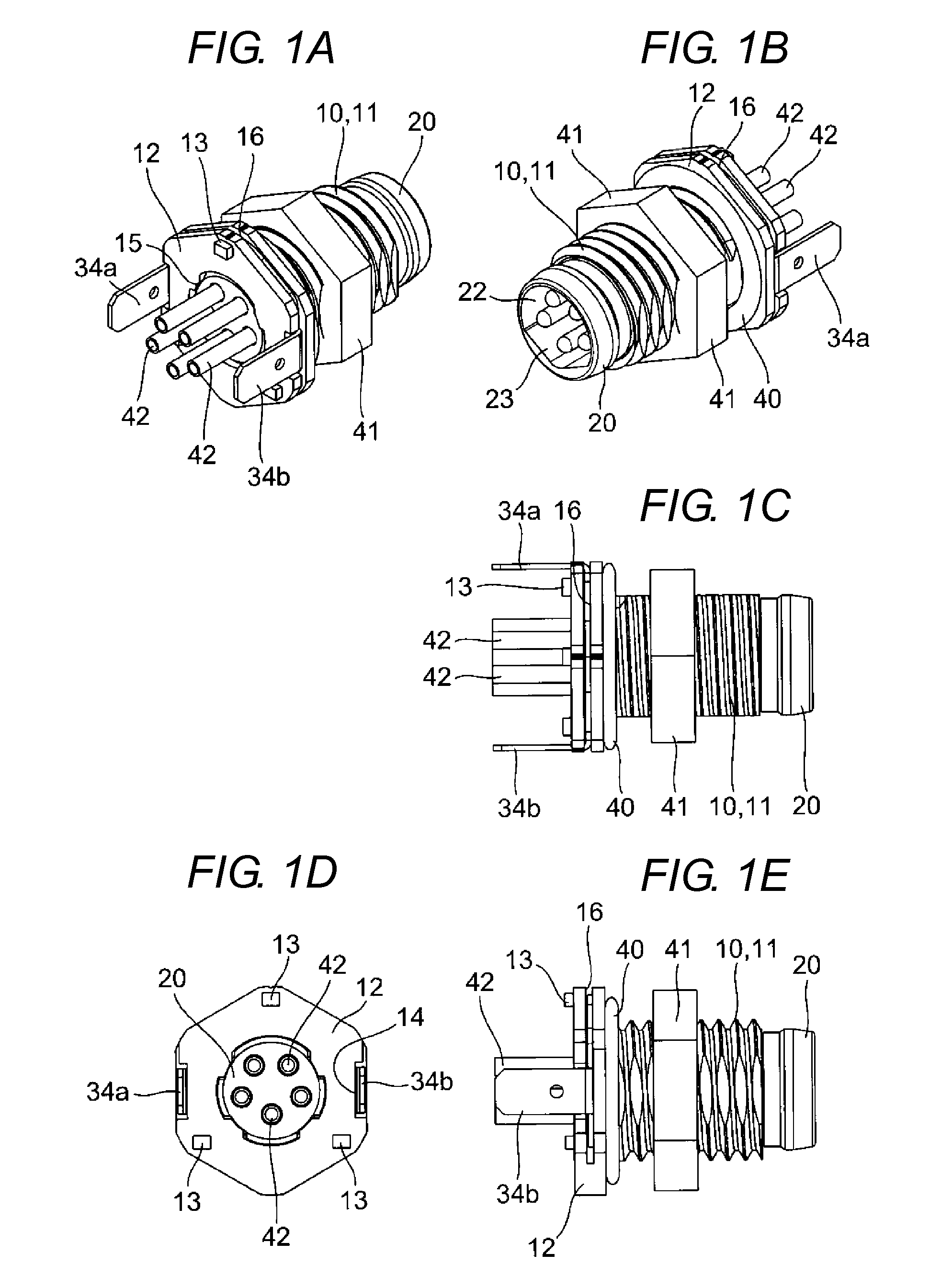
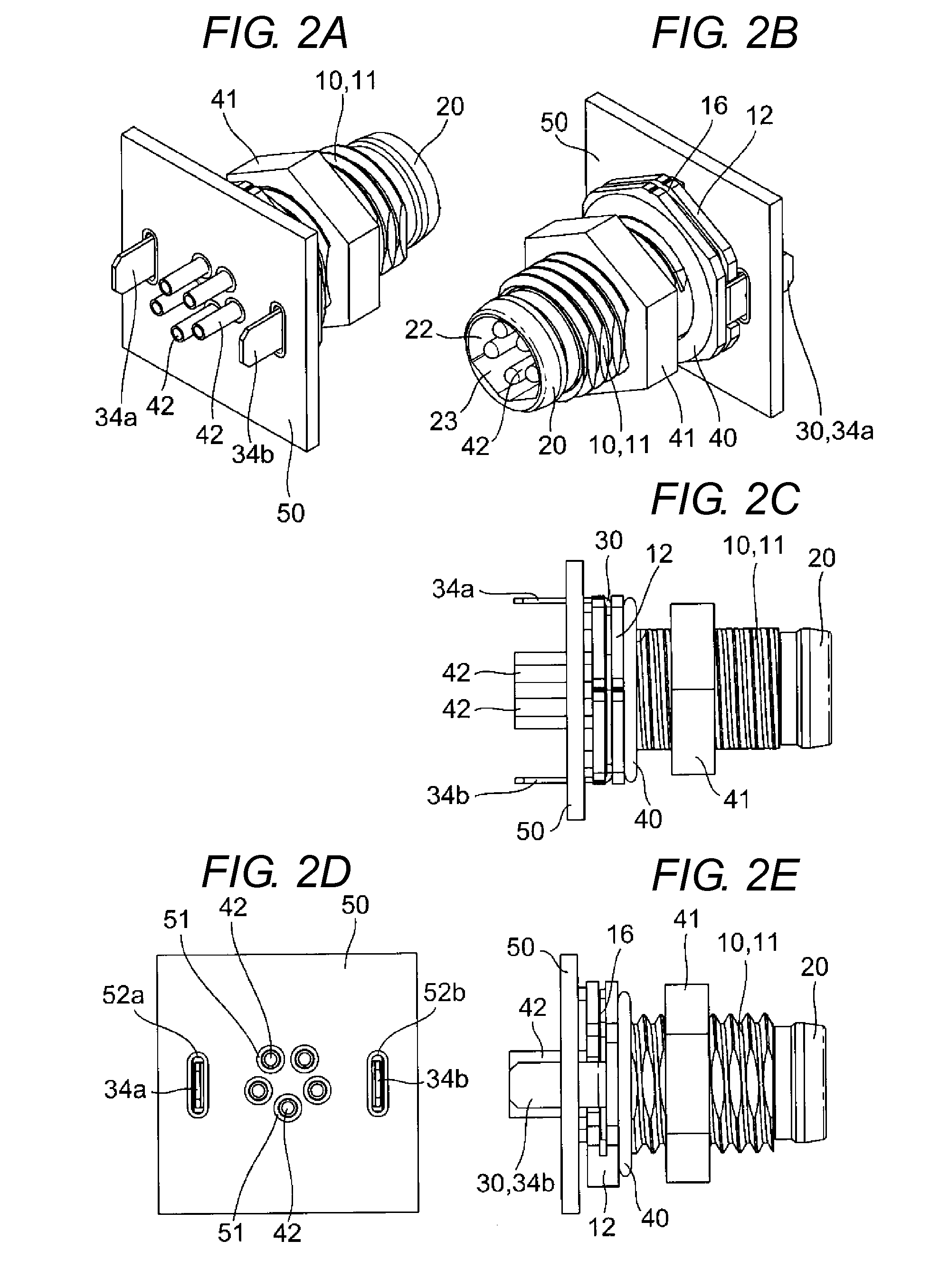
[0025]As illustrated in FIGS. 1 to 6, a connector in which a ground terminal is assembled roughly includes a connector body 10, a support 20 assembled in the connector body 10, a ground terminal 30 attached to the connector body 10, a sealing external O-ring 40 assembled in an outer circumferential surface of the connector body 10, and a nut 41 engaged with an external thread of the connector.

[0026]As illustrated in FIG. 4, the connector body 10 is a metallic cylinder including an external thread 11 on the outer circumferential surface thereof, and a guard portion 12 is provided in one end portion of the connector body 10. In the guard portion 12, standoffs 13 are projected at predetermined intervals in an outward surface edge portion. The standoffs 13 are members provided to separate the connector body 10 from a printed board 50 described later with a predetermined distance. Notches 14 with which terminal portions 34a and 34b of the ground terminal 30 engage are formed in both sid...

second embodiment

[0037] the connector, in which the central coupling portion 31 has large mechanical strength while the ground terminal 30 has the large retaining force, is advantageously obtained.

[0038]Because other configurations are substantially similar to those of the first embodiment, the identical component is designated by the identical numeral and the description is omitted.

[0039]As illustrated in FIGS. 9 and 10, a third embodiment is substantially similar to those of the first embodiment, and differs from the first embodiment in that lengths of pair of elastic arms 32a and 32b differ from each other.

third embodiment

[0040] because the latching pawl 33a having the shorter elastic arm 32a can be latched after the latching pawl 33b having the longer elastic arm 32b is latched, advantageously the work to assemble the ground terminal 30 is further facilitated to obtain the connector with high-productivity.

[0041]Because other configurations are substantially similar to those of the first embodiment, the identical component is designated by the identical numeral and the description is omitted.

[0042]As illustrated in FIGS. 11 and 12, a fourth embodiment is substantially similar to those of the first embodiment, and differs from the first embodiment in that the latching pawls are not provided in the leading end portions of the elastic arms 32a and 32b but the latching pawls 33a and 33b are provided on both sides of the projection 35 in the inner circumferential edge of the central coupling portion 31.


PUM


Abstract

A ground terminal and a connector provided therewith where the ground terminal includes a terminal portion that is electrically connected to an outside device and elastic arms that extend in an identical direction from both ends of a central coupling portion, where a pair of latching pawls is provided in at least one of an inner circumferential edge of the central coupling portion and inner circumferential edges of the elastic arms.

Description

CROSS REFERENCE TO RELATED APPLICATION[0001]This application is related to and claims the benefit of Japanese Patent Application Number 2012-256479 filed on 22 Nov. 2012, the contents of which are herein incorporated by reference in their entirety.BACKGROUND OF THE INVENTION[0002]1. TECHNICAL FIELD[0003]The present invention relates to a ground terminal, particularly to a ground terminal assembled in a connector.[0004]2. RELATED ART[0005]Conventionally, in an annular ground terminal connected to a connector, a metallic outer shell of the connector is connected to a printed board by the annular ground terminal in order to prevent an adverse effect on a signal transmitted through the connector (see, for example, U.S. Pat. No. 7,247,052).[0006]However, as illustrated in FIGS. 2 and 3 in the '052 patent, the annular ground terminal has a structure in which electric connection is established while the connector is fitted in the annular ground terminal previously mounted on the printed bo...

Claims


Application Information

Patent Timeline
Patent Type & Authority Applications(United States)
IPC IPC(8): H01R13/652
CPCH01R12/707H01R13/426H01R13/6595H01R24/86H01R13/652H01R13/6273
Inventor SASANO, NAOYAHOSHINO, HIROKAZU
Owner ORMON CORP
Why Eureka
Try Eureka